
This post is part two of a series of three by Spencer Wright, a strategist at Undercurrent, on the state of the metal 3D printing process. Yesterday’s post describes the project goals and basic technical requirements. Today’s post reflects on specific variables that affect the DMLS metal printing process. Tune back tomorrow for part three, which offers specific details of the prototyping process & an assessment of the DMLS market today.
Build orientation
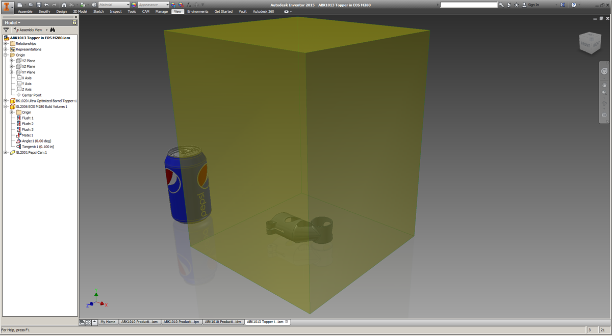
My prototyping partner, DRT Medical— Morris, prints titanium parts on an EOS M280 — the workhorse metal 3D printing machine for American job shops. Based on my research, EOS’s market penetration outmatches each of their competitors by five to one. As of November 2014, EOS only lists eighteen service-ready M280s in the US, but their data is clearly incomplete; I wouldn’t be surprised if the real number was triple that. Moreover, the vast majority of DMLS machines are purchased by OEMs, who use them for internal capacity only, and my suspicion is that the proportion of EOS machines behind closed doors is similarly large.
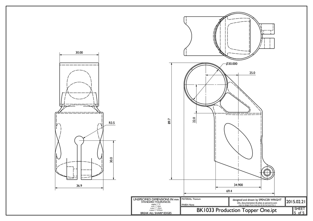
The M280’s build platform measures 250mm (x) by 250mm (y), with a maximum build height of 325mm (z), including the build plate. My part is about 70mm long (x), 37mm deep (y), and 90mm tall (z).
 A common misconception about 3D printing is that the unit cost doesn’t vary much with quantity — that printing one part is just as efficient as printing a thousand. Granted, 3D printing doesn’t require tooling, per se, but non-recurring engineering costs are absolutely to be expected. In addition to the time spent determining an optimal build configuration, there are significant changeover costs when a DMLS machine operator goes from printing in, say, titanium to stainless steel — which some low-volume service providers might do on a weekly basis. Moreover, metal 3D printing providers don’t normally print multiple orders in one build. In other words, if I buy a titanium part at the same time as another customer does, they’ll usually run those orders in two separate builds — even if both parts might fit on the build platform at the same time.
The exact math is hard to reverse-engineer, but there are generally four variables that determine the cost of a DMLS part:
- Finished part mass. There are two subcomponents here: Raw material cost, plus the time it takes the laser to sinter the part. Raw powder costs between $300 and $600 per kilogram. My part weighs about 60 grams, which puts the material cost in the neighborhood of $30. But that 60 grams will take about eight hours to sinter, and the cost of sintering time adds up quickly. As a rough guide, expect to spend on the order of $100–200 per hour for part build time.
- Support structure mass. DMLS parts require solid support structures to tie them to the build platform, and those structures are made of the same metal powder that the part is. If your part has a lot of overhanging geometry or requires additional support structures for other reasons, you’ll pay for those (and the time it takes to sinter them) as well.
- Part height. Across all types of manufacturing, capital expenses (tooling, etc.) are paid off over a period of years. In DMLS, part height correlates directly with time spent recoating the platform with new powder, and that, in turn, equates to a higher tooling cost that the supplier needs to pay off during your build. As a result, designers are incentivized to orient their parts as close to the build platform as possible, to reduce build height and, hence, reduce recoating time.
- Number of parts per build. Because the setup and powder recoat time can be shared across multiple parts, buying in batches (when possible) will generally be less expensive than buying one-offs.
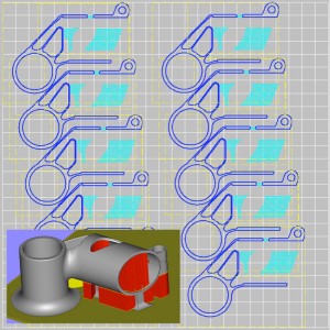
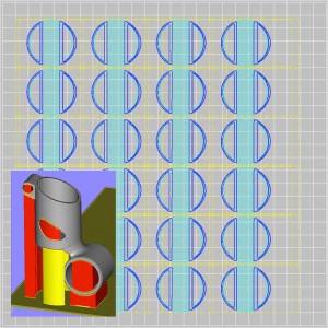
In my case, those last two factors act directly against each other. If I orient the part on its side, I can fit about 10 parts per platform, with a ~40 hour build time — about 4 hours apiece. But if I orient them vertically (upside-down ends up being more favorable), I can print 24 parts in a ~85 hour build — about 3.5 hours per part.
At this point, Dustin and I spent some time thinking through the manufacturing process chains for each of these configurations. It’s very likely that we’ll end up needing to machine the inner diameters of both of the part’s cylinders, and we wanted that process to be straightforward and involve as little custom tooling as possible (post-processing DMLS parts often requires extensive custom tooling). As far as we could tell, Build Configuration 2 was going to be slightly easier — mostly because the long ID could be machined while the part was still on the build platform. But the difference was very difficult to quantify, and, in the end, our build orientation was determined for a much simpler reason: powder availability.
The DMLS powder market is, like most things in this industry, changing rapidly (for anyone interested in a geographical representation of the additive supply chain, see this great map). Powdered metal is expensive to produce, and the particle size, shape, and consistency are critical to finished part characteristics. And while prices are going down rapidly (double digit percentages year-over-year, I’m told), service providers are still stuck with having a large chunk of money tied up in raw powder powder at any given moment. Add in lead times, and the fact that titanium powder isn’t particularly fun to handle, and you can see why job shops would only want to keep as much powder on hand as they absolutely need.
In the end, we ended up building my part on its side simply because DRT was getting towards the end of a batch of powder, and the taller orientation was going to require more than they had on hand. Which is possibly, given the small quantities these parts will probably be produced in, the right orientation anyway — and was a less expensive build to boot.
At this point, our goals were explicit: Determine the minimum amount of post processing necessary to produce a working part.
Stress & build failure
It’s critical to remember that 3D printed parts move as you print them. The same is the case with other manufacturing methods as well (injection molded parts shrink as they cool, machined parts warp as they’re cut, etc.), but DMLS creates extreme thermal gradients, and the net effect is that stresses are built into the part layer by layer.
Predicting built-in stresses is an incredibly difficult task, and is the topic of a lot of basic research. At the moment, the best we can hope is to analyze and understand the stresses that are built into parts once they’re complete; predicting them before they happen is still a long way off.
Despite the fact that stress prediction is very much a dark art, the correlation between laser sintering and welding is not a trivial one; many of the same principles apply to both. But when approaching a new part, it’s almost always the case that the best way to deal with potential problems is through trial and error — and then adding and removing support structures as necessary.
This is a key point: powder bed fusion involves welding your part to the machine while you build it. The build will definitely fail if the part lifts off the build platform (when this happens, the recoater blade strikes the part; in general it doesn’t damage the machine, but I’m told it can be… exciting), so a lot of effort goes into designing clever — and hopefully not too massive — solid and lattice support structures to keep the part where it’s supposed to be.
Even if the build itself doesn’t fail, internal stresses can still render it unusable. This is why most parts are stress-relieved (a heat treatment process) after they’re built and before they’re removed from the build plate; doing so allows the crystalline structure to relax, preventing failure later.
Going into the build process, I was warned many times that cylinders oriented parallel to the build plate are notoriously difficult to build. The stress profile around the circumference of the cylinder will tend to vary widely, and the result is that you generally wind up with a big oval. But other than orienting the part at a 45° angle to the platform (and risk ovalizing both cylinders), our options on this part were limited. So, we started as simply as possible, and iterated as needed.
See part three to learn about the process and the path forward.
Thanks
First, thanks to Dustin Lindley (of UCRI) and Dave Bartosik (of DRT — Morris), without whom all the cool stuff described above would have never happened. Thanks also to Greg Morris (who originally connected me with Dustin, Dave, and Chuck Hansford at DRT), to Clay Jones and Jordan Husney for their creative inspiration and infectious enthusiasm throughout the process, and to Clay Jones and Mike DiGiulio for reading early drafts.
Lastly, thanks to Undercurrent, which is providing critical funding for this project — and which I am proud to call home.