
Free guide to
Autodesk Netfabb premium
Autodesk’s Netfabb software is an end-to-end toolset for streamlining the additive manufacturing workflow. The software is targeted at professionals, such as engineers and designers, and businesses in the AM industry. However, Netfabb’s learning curve is not too steep for hobbyists either.
Netfabb is currently available in two versions, Premium and Ultimate. This is a guide to Netfabb Premium, however, it is also useful for either version of Netfabb.
According to Autodesk, the aim of Netfabb is a 3D printing software for streamlining the AM workflow. To ensure this, Netfabb Premium is equipped with the necessary tools for the AM production cycle.
Netfabb tools allow users to repair CAD models, edit triangle meshes, optimize STL topology, manage a fleet of 3D printers, and much more. Moreover, Netfabb can be used alongside Autodesk Fusion 360, thus incorporating design capabilities.
These features make Netfabb Premium an attractive choice, particularly, for individual users, research institutes, and small businesses, such as 3D printing service bureaus and print farms.
In recent years, Netfabb has become an essential additive manufacturing tool for architects, medical professionals, and aerospace and automotive engineers.
This guide explains the most important features Netfabb Premium has for designers, and engineers.
How to use My Machines
In this section, we will talk about a key feature of Netfabb Premium, My Machines, which lets users optimize 3D models for various 3D printers, all in a single workspace. The My Machines feature can be of great value to organizations and businesses who run multiple machines. Netfabb integrates all its features with different 3D printers using the My Machines functionality. By doing this it removes extra steps from the AM workflow, thus minimising production time and labour costs.
3D printers from various manufacturers can be added to the Netfabb workspace via the My Machines dialog. Out of the box Netfabb Premium includes 3D printers from 40+ manufacturers such as Formlabs, HP, EOS and others. But the software is not limited to these pre-installed machines. More 3D printers can be added using the ‘Create Custom Parameters’. This could be particularly beneficial for design studios who use their own any of the growing number of 3D printers available.
With the help of My Machines functionality, users can optimize their 3D printing workflow for a variety of purposes. For example, a specific CAD file, depending on its geometry and structure, may be best for SLS, but perhaps not ideal for SLA or DLP. Alternatively, a user may have various 3D printers, all appropriate for different tasks – one for prototyping and another for end-use manufacturing. With the help of My Machines, the whole manufacturing cycle can be streamlined.
Let’s say a user has an .stl file of a dental prosthetic and this model requires prototyping before functional manufacturing. Using the My Machine feature, users can first send the model for prototyping to a precision 3D printer like the Form 2. And once the quality standards are satisfactory, a functional prosthetic can be produced with other technologies.
Furthermore, with My Machines, users can group 3D printers by materials instead of technology. By doing this, components of a multi-material design can be manufactured in different materials, using diverse 3D printing methods. And all such tasks can be managed with Netfabb.
Moreover, various templates for automation can be added to the workflow. These templates can be of pre-defined repair scripts, support scripts. Having such templates saves time and effort. Hence, a Form 2 printer can have unique repair script, and an HP MultiJet Fusion can have its own. And when an .stl file is added the repair script automatically fixes the errors using the custom script.
In addition to this, each machine (where applicable) can be linked to its native software through My Machines. For example, Formlabs can be connected with Preform. Any 3D model can be sent directly from Netfabb to Preform, and from Preform for 3D printing. In this way, Netfabb forms a kind of network of software and hardware to streamline the workflow.
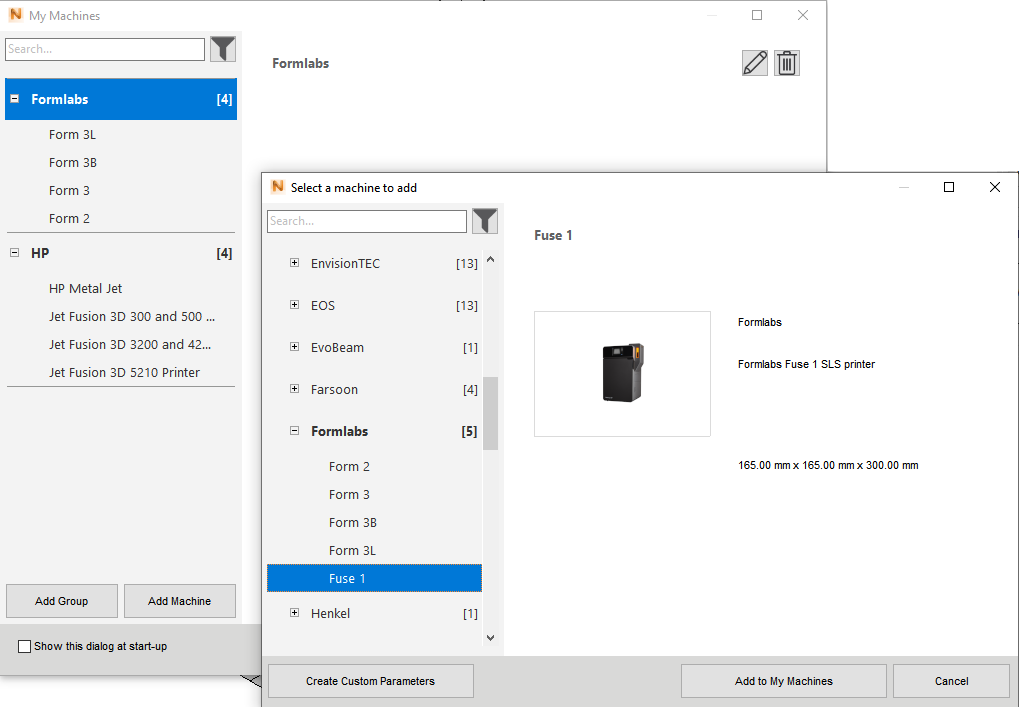 The My Machines dialog in Netfabb. Image via Autodesk.
How to analyse an STL file
STL, OBJ and other mesh file formats need to be examined for geometrical anomalies in order to minimise print failures. Here we look at how to analyse and fix 3D models in Netfabb.
One of the primary functions of Netfabb is repairing files. On the face of it, a CAD model may look perfect. But the model itself does not guarantee printability, nor can it predict errors that appear in the STL format. Therefore, after the modelling stage, the printability of a 3D model needs to be determined. This can be done with the help of various analysis tools offered by Netfabb.
Netfabb can generate a variety of detailed reports and calculations, such a mesh comparison between two identical models, wall thickness, support volume, and cost analysis.
Depending on the purpose of manufacturing, the triangular mesh of a 3D model may need to be optimized. For example, end-use parts need to be manufactured in exact detail, as discrepancies lead to quality assurance problems. Furthermore, to save costs and time it is important that a part is 3D printed accurately in the first attempt.
Netfabb’s analysis tools help users determine the printability of parts to guarantee that the manufacturing cost and time will be kept to minimum.
In Netfabb, mesh level detail can be refined to ensure that a part will be manufactured in high detail (depending on the 3D printer used). Furthermore, a wall thickness report generated by Netfabb can help designers solve issues related to surface quality. Wall thickness (the difference between a given surface and its opposite sheer surface) of a part must be a certain magnitude for a 3D model to be printable and durable. But, of course, printability will also depend on the 3D printing technology used for manufacturing the model.
Another important analysis tool in Netfabb is the collision detection tool, which examines whether two parts are in contact with each other and prevents different models from merging with each other during the printing process.
How to repair an STL file (Part 1)
An STL file can have various complications, which can make it unprintable. To make things easier for designers and engineers working in the AM industry, damaged 3D files can be quickly repaired, automatically or manually, in Netfabb and be print ready.
Some of the typical glitches in an STL file include holes or gaps in a mesh, multiple miniscule shells, and degenerated faces.
Once a part has been opened with Netfabb, users can enter the repair module by selecting “Repair Part” within the “Prepare” panel, which shows detailed statistics of the model, and displays the damaged areas. The repair module can generate this data even if the model is damaged to such an extent that it is not visible in the workspace.
The ‘Repair Scripts’ tab has multiple filters that can be applied to fix a model. Pre-defined scripts such as ‘Default Repair’, ‘Simple Repair’ and ‘Extended Repair’ are available, which can restore a 3D model instantly. But the automatic repair tool does not constrain the users to choose only from predetermined scripts. Users also have control over which type of scripts to run for what damage. Moreover, users can run single scripts of their own choice, or make their own group of repair scripts, which can be linked to 3D printers added to My Machines.
For added ease of use and efficiency, repairs can be done at the file import dialog so that when a faulty model is added to a workspace, repairs are automatically applied. In addition, specific repair scripts can be assigned to 3D printers in the My Machine dialog.
If desired manual repairs can be carried out in the repair module. Each triangle in a mesh can be fixed individually or in groups. This method may take a lot of time, but it gives full control to experts who may have to recover badly damaged files.
All the repair tools mentioned above can be used to fix multiple models or large batches in a single workspace.
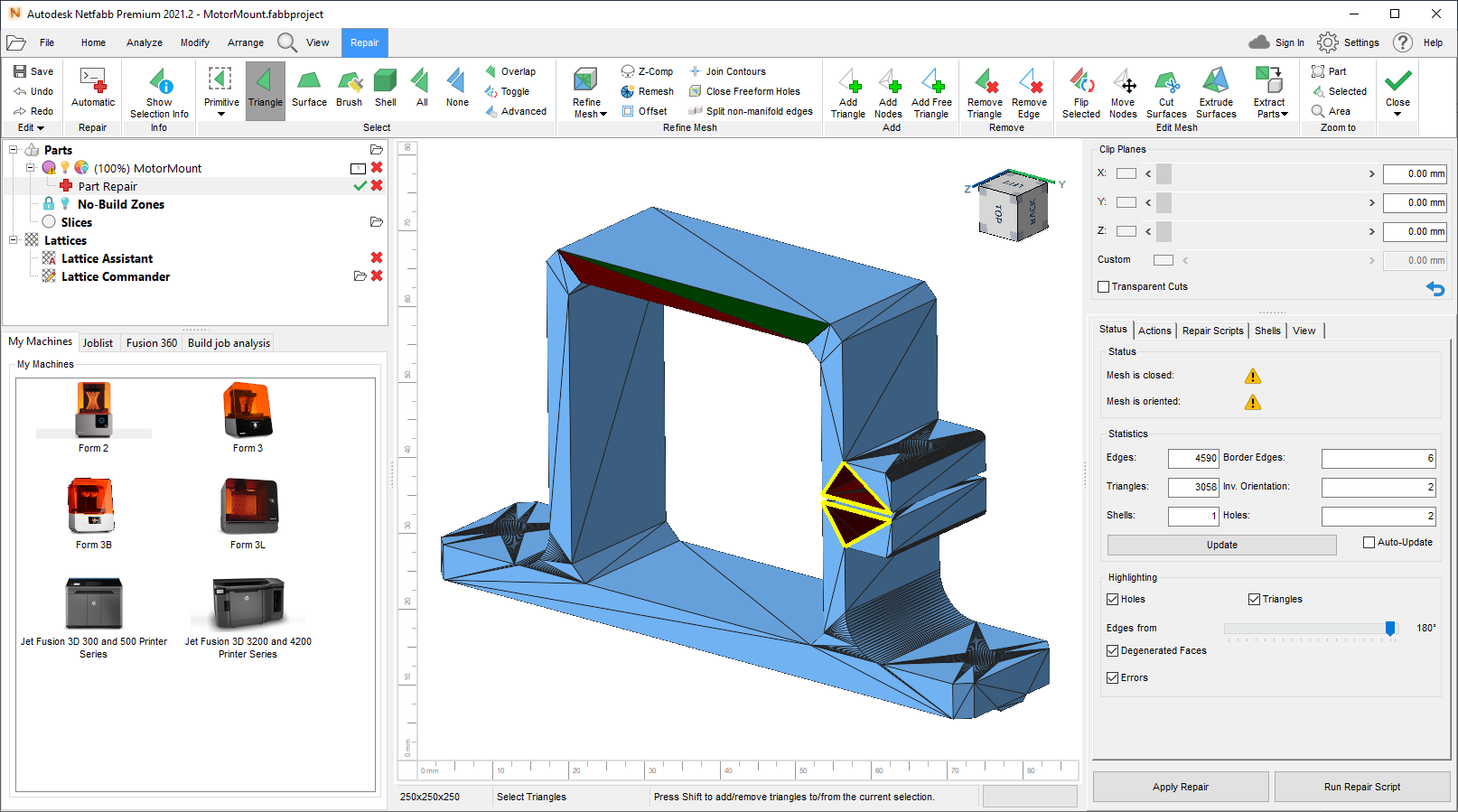 Netfabb’s repair module. Image via Autodesk
How to repair an STL file (Part 2)
Here, we will talk about the theory behind triangular meshes and how to repair them. Readers averse to technical descriptions can skip to the second part of this section where we discuss various repair scripts and how each can be used to fix mesh errors.
Most designers, using a parametric design tool, will not see how the model shape is represented by the triangular mesh. When a CAD file is converted to an .stl or .obj, the software takes a parametric 3D model and translates it into a tessellation of triangles.
A mesh is a network of repeated forms connected to each other without gaps and overlaps. In 3D modelling polygonal tessellations are used to represent a 3D form. These are known as polygonal meshes. The most common type of mesh used in 3D printing technology is the triangular mesh, mostly used in the STL file format. The mesh approximates the original shape using triangles.
In a triangular mesh, triangles are connected in a 3D space to form a surface. It is a network of triangles, where each triangle has an edge, a face, and a vertex. Each vertex is connected to at least six edges.
A mesh can convey the information about the geometry and topology of the 3D model, in a logical and consistent manner, because each triangle in a mesh agrees with neighbouring triangles about their orientation, or which points inwards or outwards.
One way the geometrical information is represented is whether a vertex (the point where two lines meet) is convex or concave. In a polygon, like a triangle, this information is expressed by the internal and external angle of the shape. If the internal angle of a triangle is less than 180° then it is convex, otherwise it is concave. The orientation of the face is coded using clockwise and anticlockwise direction of the ABC vertices. For example, an outward face will be marked with ABC sequence, whereas an inward face will have ACB direction of the vector.
During the conversion from a CAD file to .stl or .obj errors can arise in the mesh topology. These errors can only be fixed using a tool that allows the manipulation of meshes. It should be noted here that such a tool focuses on mesh topology or how triangles are connected with each other. It does not address the issue of geometry, which concerns where the triangles are located in 3D space. This is done using mesh editing tools. Whereas, a mesh repair tool makes adjustments to the information in the triangular mesh.
In mesh repairing, the main concern is how the triangles combine to close the regions of space and whether they are in proper relation to each other.
Common problems which could arise in a mesh are gaps between triangles, erroneous orientation of triangles, holes in a mesh, overlapping triangles, flipped triangles, degenerate faces, and excess shells.
When a 3D model is added to Netfabb, a dialog screen appears which notifies the user if the model needs repairs. A large warning sign is also displayed at the right corner of the build plate if a file has errors. This signals that before making any changes to the model, the user should first repair it.
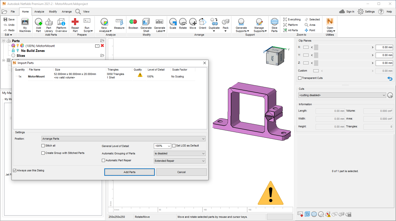 Loading a problematic STL file displays a Quality Warning within the Import Parts dialog and on canvas. Image via Autodesk
Using Netfabb Premium’s repair module, such errors can be fixed either manually or automatically. Errors can be repaired by selecting suitable scripts and running them to fix errors automatically, or each triangle can be selected separately, and fixed individually.
Some of the automated scripts available in Netfabb are:
- Stitch Triangles: closes the gap between two triangles.
- Remove Double Triangles: removes overlapping triangles.
- Fix Flipped Triangles: a triangle which should be facing outwards due to some error is flipped. This script can change the orientation of the triangle, from external to internal and vice versa.
- Close All Holes: there may be holes in a model due to missing triangles which can be fixed by running this script.
- Remove Degenerate Surfaces: triangles that are too small or contain no information can be removed.
- Remove Tiny Shells: ideally, an STL model should be made of a single shell, because multiple shells can cause printability problems. This script removes minute shells.
- Wrap Part Surface: this can combine multiple shells into a single piece.
Netfabb has pre-set automatic repairs which either contain all the above-mentioned repair scripts or some of them. Pre-defined repair settings are ‘Default Repair’, ‘Simple Repair’, and ‘Extended Repair’. These are general groups which contain specific repair scripts. Netfabb Premium users can create their own group of repair settings with scripts of their choice. These groups can be saved and reloaded for future use.
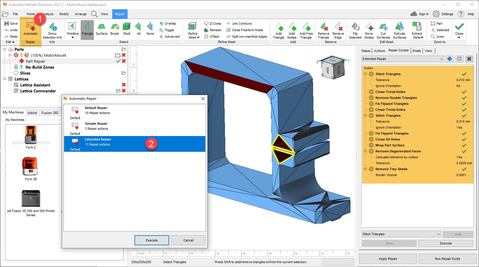 Highlight of various pre-defined repair actions within the automatic scripts available in Netfabb. Image via Autodesk
In the AM industry, one of the problems 3D printing professionals encounter is dealing with the overabundance of CAD file formats. This can often slow things down as each file may need additional software.
In this chapter, we will talk about all the third-party file formats supported by Netfabb and its own native file format.
Netfabb User Interface
In Netfabb, User Interface (UI) has been thoroughly worked and updated. Autodesk is trying to bring Netfabb out of the expert-only category to a wider audience. Changes to the UI are a welcome move in this direction.
Since Autodesk acquired Netfabb back in 2015, many aspects of the interface have been changed, almost close to a complete redesign. Though, seasoned users of the software may find it difficult to adjust to the latest additions, for new users Netfabb will likely feel more intuitive. This is because the UI of the edition is much closer to other popular software in 3D printing, such as Autodesk’s Fusion 360.
The updated UI includes the My Machines dialog, one of the novel features added to Netfabb Premium. As discussed in Chapter One, My Machines allows users add to various 3D printers for different projects. The machines are added with the picture of the original 3D printer. Having such visual aid can make navigation around an opened project easier. Furthermore, the build plate visualization in Netfabb Premium mimics the original 3D printer. Another addition to the UI is the ‘Joblist’ tab, which shows active tasks in Netfabb.
The project tree structure, visible on the left side of Netfabb’s screen can be used to manage the workspace. Machines, parts, and slices can be organized using the tree structure, which can help with handling various on-going tasks with greater ease.
Despite all the updates the Netfabb UI is not overly crowded. Users can adjust the layout according to their preference. In the ‘System’ tab, Netfabb has ‘Reset Window Layout’. Here, ‘left layout’, ‘right layout’ or the default ‘center layout’ can be chosen. Moreover, users can ‘unlock’ the views to place them anywhere on the screen. Users can also create a custom ribbon and create a personalized experience.
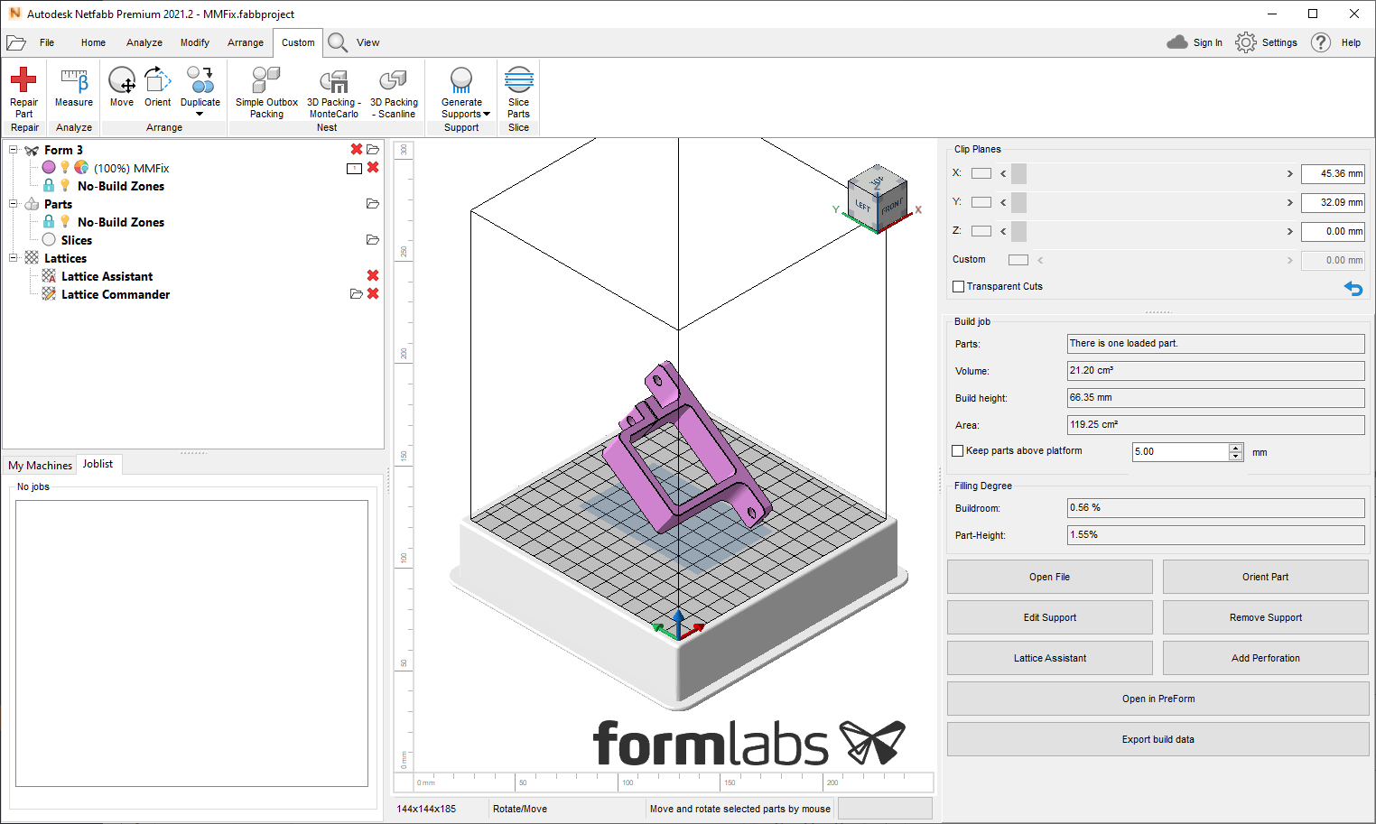 The default center layout of Netfabb’ User Interface with a part loaded in a Formlabs Form 3 printer and a customized ribbon. Image via Autodesk
How to handle 3D files for additive manufacturing
In a demanding 3D printing business, as more machines, parts, and slices are added to the Netfabb workspace, a project might become very large, taking more time to complete. The progress of the projects in Netfabb can be saved in the ‘Fabbproject’ file. The Fabbproject compiles machines, parts, slices, and supports into a single file and saves it.
The Fabbproject can save changes to a part and project separately. Users can make changes to a model without affecting the original file and save these changes to the Fabbproject. In relation to this is the file restoration function, which has been added to the latest edition of Netfabb. The restoration feature can recover unsaved changes to the project. Another benefit of saving a project in Netfabb is that users don’t have to create copies of modified .stl files outside of the Netfabb environment. This way the master copy of a 3D model is kept safe.
There is an abundance of 3D modelling software available on the market such as SolidWorks, Rhino, Catia, and Siemens NX, among others. All these software use specific file formats to store a 3D model, for example, SolidWorks generates .sldprt and .sldasm files, Rhino generates .3dm files.
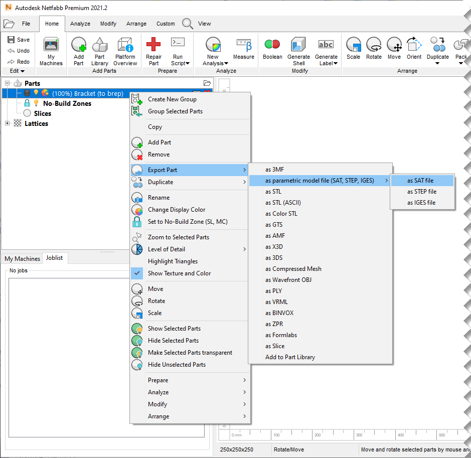
Netfabb can handle the above-mentioned files and many other popular 3D file formats. For example, users can import CAD files either as a mesh or as parametric files. These files can then be exported either as parametric files in SAT, STEP, and IGES or as 3D printable mesh files like 3MF, .stl, .obj, or Formlabs native format.
The following example gives a better idea of how dynamic Netfabb’s file handler is. A popular parametric CAD software, SolidWorks, saves a whole part in assemblies, as a single file, in .sldasm. In this file format, each part of a model exists as a separate unit. Netfabb can import a .sldasm file either as a mesh or a parametric file. Furthermore, it gives the users the option to separate the assemblies from the whole and edit or 3D print them separately.
Moreover, these assemblies can be exported as separate CAD or 3D printable files in other file formats. In combination with Netfabb’s other features such as My Machine, mesh repair and editing, support generations, Netfabb’s file handler can prove a powerful tool. Not many 3D software have such capabilities.
Netfabb also has a file preview browser, which lets user quickly view and open .stl, .obj and slice files. The preview browser is particularly helpful for handling a massive collection of 3D models stored in a single folder. For example, most current software will only show the icon of 3D files and not a view of the model itself. This makes it difficult to find the desired 3D model in a folder with a large number of files,
With the help of Netfabb’s preview browser users can see the models themselves. Furthermore, as some older versions of operating system still lack the 3D model view function, so Netfabb’s file preview browser can be used skim through all the 3D files and open them as needed. The preview browser can be of particular value to businesses who maintain a digital inventory.
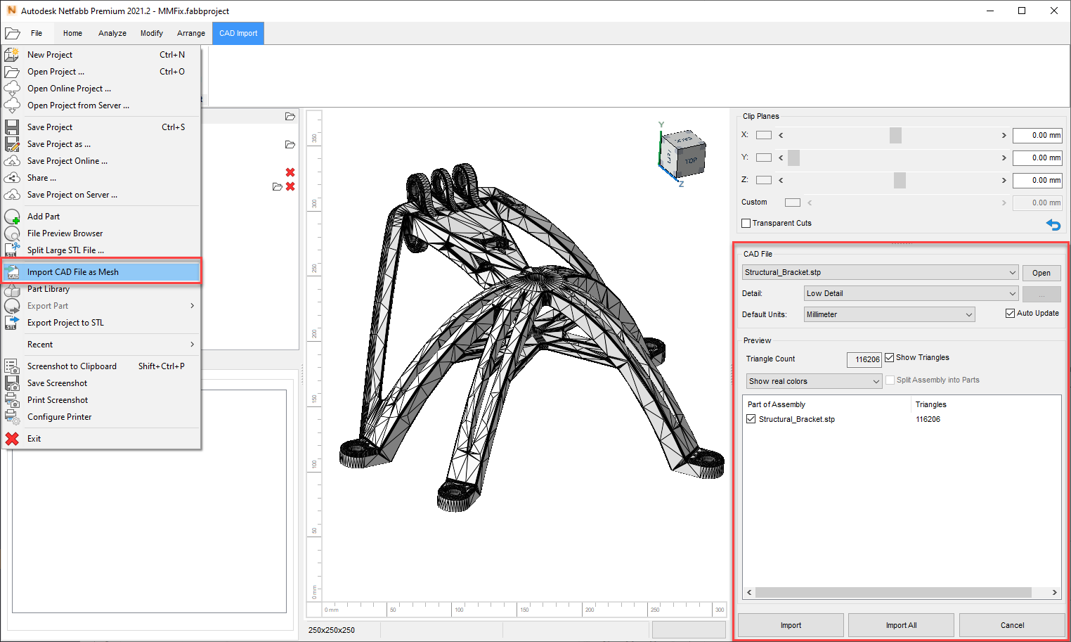 Importing CAD files into Netfabb. Image via Autodesk
How to use A360 Cloud with Netfabb?
Autodesk has its own cloud tool for 3D design projects, the A360 Cloud, which is integrated with Netfabb and Autodesk’s other 3D software. The A360 Cloud can be used to share 3D models with employees and clients all around the world.
Cloud computing can make project and file handling more efficient. As there is no need to share physical files through storage devices, edits can be made in real-time with the help of a cloud platform.
In 3D printing, one of the ways that businesses streamline projects is by sharing and viewing 3D projects and 3D files with remote clients. A cloud platform can be used to satisfy clients’ demands in the 3D modelling stage.
In Netfabb, various file types can be added to the build platform and then shared to the A360 Cloud. These files can be .stl, or .obj. Using the ‘import CAD file’ button, parametric CAD and mesh files can also be shared, though A360 does not give a mesh or parametric view of the 3D model.
The A360 viewer tool can be particularly helpful in educational institutes, as it lets the users add comments, mark up, and feedback.
The model handling tools available in the A360 viewer are calibration, measurement, and sectioning tool which lets the user clip planes to view inside of a model.
In addition to this, an entire Netfabb project can be saved on the cloud, which can be shared and downloaded. The project is saved as a .netfabbonline file.
The A360 Cloud is free and comes with 5 GB storage. However, businesses and institutes with larger teams might prefer BIM 360 Team or Fusion Team subscription. Both are available for £8/month and come with a 500 GB storage.
Viewing 3D models in Netfabb
Flexible model viewing options are an important tool for a designer. While inspecting, arranging, or fixing a 3D object shifting viewpoints of a model becomes essential.
Netfabb has a number of tools to facilitate a designer’s perspective of the 3D model.
In addition to the usual left, right, top, bottom perspective, Netfabb also has the isometric view which shows a model from the front left top corner. Isometric view (or projection) all the angles between the projection of the axes are 120°. This view is preferred in engineering illustrations as it represents the dimension of all sides accurately.
Some parts can have millions of triangles in a mesh. This is common with objects which are 3D scanned. The detail level of such parts is rather extraordinary. But such files are also too large to run smoothly in a 3D software. In Netfabb ‘level of detail’ can be set to make the 3D model quicker to process. This is especially helpful if there are a lot of parts opened on the platform.
Moreover, a low-level detail view is also good for estimating how much quality will be compromised if triangles are reduced in mesh editing. It should be noted that changing the level of details will not affect the original part.
The level of details option can be coupled with ‘highlight triangles’ view which shows a mesh of triangle over the 3D model. However, this mesh is different from the underlying triangular mesh of the object, which is displayed in the repair or manipulate mesh module.
Furthermore, insides of a 3D model can also be seen by using the Clip planes tool located at the right side of the screen. A section view exposes the insides of the 3D model. Internal walls of the model can be highlighted using the ‘Highlight Backfaces’.
One of the most convenient zooming options include ‘zoom to part’ which quickly bring the object to the screen. If a part is extremely small and is not visible when it is imported, ‘zoom to part’ can be of great assistance.
‘Show part names’ option in the view tab, displays a name and measurement tag of each model on the platform. This can be handy if there are a lot of parts packed on the build platform. Moreover, multiple parts can be selected and turned transparent or hidden from the view using the ‘make selected parts transparent’ or ‘hide selected parts’ options.
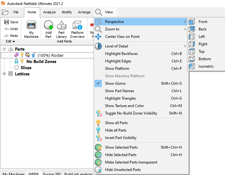 Various view options in Netfabb. Image via Autodesk
How to cut a 3D model
A manufacturing constraint associated with the additive process is the build size of 3D printers. Most 3D printers have a limited build volume, in particular, desktop machines and metal 3D printers. This can make prototyping or manufacturing of large parts difficult.
A way to overcome this difficulty is to divide large parts into smaller pieces which can be assembled after fabrication. Such an option can, in theory, make the build size of 3D printers limitless. However, Netfabb has many cuttings tool just for this purpose.
A 3D model can be cut into pieces along the X, Y or Z axes, to divide a model into manageable parts. All the pieces can be arranged on the build plate using Netfabb’s batch printing tools. One of the advantages of the cut feature in Netfabb is that users do not have to go a step back to the design stage to make minor changes like flattening the surface of a model. Using Netfabb, cuts can be made using a cutting plane, or various polygonal shapes, or a circle.
The cut feature brings various advantages to the manufacturing process. Suppose an automotive design firm wants to print a life-size bumper cover, the cutting feature in the Netfabb software can help build the geometry on a single 3D printer. Afterwards, the model can be put together with glue or assembly joints.
Moreover, before 3D printing a full model, a designer may want to test the printability of a specific portion of the model. A cut can be made to this area for test printing. This can ensure that the full 3D print is successful in the first attempt, saving time and costs to 3D print large objects.
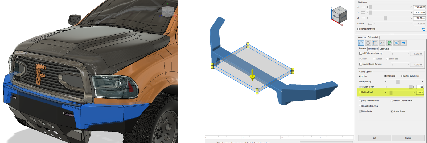 A part designated in Fusion 360 being cut in Netfabb using the polygon cut with cutting depth option. Image via Autodesk
3 – Editing mesh and surfaces
Making edits to mesh files is one of the vital steps in preparing 3D printing files. Mesh editing can save countless hours that would go into redesigning an already existing 3D model.
Here, we will discuss various mesh editing tools offered by Netfabb to modify models and prepare them for various 3D printing technologies such as SLA/DLP. This chapter also covers mesh comparison tool which can be of great value to businesses who need to discuss precise details of 3D models with their clients.
How to edit STL meshes
For traditional manufacturing processes material handling, tooling, and labor expertise, is an important part of the manufacturing operation. Furthermore, lead times in such processes can be significantly long, as raw materials need to be procured and production equipment must be planned. For example, a casting process will, first, require manufacturing of molds, and in lost wax casting, a mold is needed to manufacture each separate part, adding to production time.
For CNC machining a toolpath needs to be planned, and other factors must be considered such as tooling, sequence, and access. In such cases, manufacturing of complex parts may take longer.
In contrast to this, the method of additive manufacturing is single step production, from design to manufacturing and complexity of the part does not affect the lead time.
However, one of the problems in 3D printing is that manufacturing guidelines are highly machine and material specific. Therefore, it is possible that a 3D model is ideal for printing in SLS but not in FDM.
Another problem that could arise is that the process parameters of one machine may not be compatible with another machine. For example, a part manufactured in EOS M270 DMLS printer, may not be printable with the best of results in the next version of the 3D printer, the EOS M290. This could simply be due to a minor modification such as the improved inert gas flow control of the EOS M290.
Therefore, in the single step manufacturing paradigm like AM, the design stage receives the most attention and therefore a mesh editing tool becomes necessary.
Furthermore, there are a plethora of .stl and .obj files available over the internet. Such files include dental and anatomical models, which may occasionally require editing.
A 3D model is built using geometric primitives, shapes such as a cube, cylinder, and torus. These primitive shapes are the metadata of the 3D model. After the creation of a 3D model in software like Fusion 360, a CAD file is exported to .stl or .obj for 3D printing. These files translate a 3D model into a triangular mesh and the metadata of the 3D model is lost. Hence, in .stl, .obj, and other similar files the underlying parametric geometry cannot be accessed for the purpose of editing.
Editing of .stl and .obj files is possible by making changes to the triangular mesh and for businesses with a digital inventory a mesh editing tool becomes necessary.
Netfabb allows the user to edit 3D models by manipulating the triangular mesh.
Mesh Manipulation module is different from the Repair module. The repair function in Netfabb automatically fixes models for errors. Whereas mesh manipulation function allows for additional manually control over the mesh.
Several editing options are available in Netfabb’s Repair and Mesh Manipulation modules. This includes refining the mesh for precision 3D printing, adding, and removing triangles, smoothening the mesh, cutting and extruding surface. Add node function within the Repair module gives users more control over the manipulation of a mesh. With the help of the Add Node tool, a precise point can be indicated to generate new triangles.
Triangles can be added to the tessellation to increase the resolution of the 3D prints. This can be done individually or automatically. However, increasing the number of triangles in a mesh will make a 3D file larger which could take longer to slice and add support structures.
On the other hand, triangles in a mesh can also be reduced. This will also shrink the file size. It should be noted that reducing the number of triangles can depreciate the quality of a 3D model. But, in many cases, mesh file size can be reduced without influencing the physical properties of the part in accordance with tolerances.
A few other mesh editing tools in Netfabb include surface cutting, extruding triangles, and smoothing.
A scanned object may contain unnecessary triangles which gives objects sharp edges. Sharp edges of an object can be smoothened by using the ‘Smoothing’ tab in the Mesh Manipulation module. Furthermore, an advanced ‘Remesh’ tab is also available, which restructures the mesh in a more uniform way and can preserve the crucial geometrical details of the object.
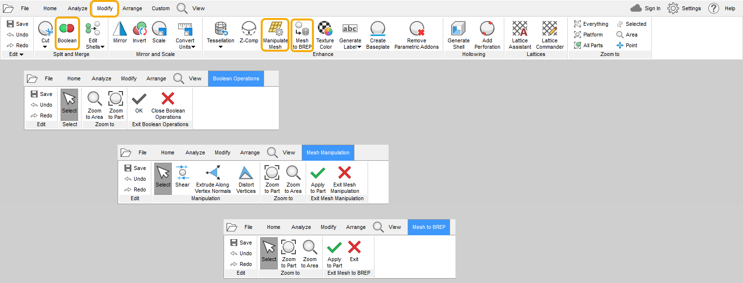 Various mesh editing access points from Netfabb’ Modify tab. Image via Autodesk
A model may be designed as individual parts and then exported to an .stl file not as a single piece but as separate shells. However, a designer may not intend this, because separate shells in a single model can cause print failures. Netfabb can split separate shells into parts which can be joined together using the Boolean operation accessible within the Modify tab, Split and Merge panel. This operation creates a single uniform mesh from separate parts.
In addition to this, a mesh can be converted to a BREP (boundary representation) file and later can be exported as a .step, .sat or .iges file.
 A mesh part converted to BREP being exported as a .sat file out of Netfabb. Image via Autodesk
How to hollow an STL file
In 3D printing solid models are generally printed with infills.
FDM/FFF printers fill the insides of the 3D model using various types of infills such as honeycomb or gyroid structures based on the toolpath data as defined within the Gcode file.
SLA/DLP 3D printers do not need a toolpath file. They fill the insides of a 3D model based on the slice file with liquid resin. The resin hardens and produces a robust solid model. If the CAD or Mesh file is solid, this will be reflected in the slice file as well. A solid object, when sliced, will only have the exterior contour for each slice and 3D printing such an object will increases the print time and will consume large volumes of resin. In many cases, filling a model with resin would be completely unnecessary.
One way out of this problem is hollowing the 3D model, which leaves only the exterior walls with a small thickness. And the model can be 3D printed much faster. But in order not to encapsulate the liquid resin within the hollowed 3D model, there needs to be holes where the resin can exit the enclosure. Usually special software is used which can create holes or other perforations to release the unused liquid resin during SLA/DLP printing process.
As Netfabb is an all in one 3D printing software solution, it includes a ‘Generate Shell’ feature which automatically hollows a 3D model, with a custom defined wall thickness. Furthermore, Netfabb Premium’s ‘Add Perforation’ tool helps users automatically generate holes in the shell for resin discharge.
The Add perforation tool also has a ‘generate plug’ option. This can create same size fillings or include a clearance to account for glue thickness for the hole made with the perforation tool. The plugs can be 3D printed and used to cork the holes.
Another way of creating an outlet for liquid resin is by cutting a superfluous part of a model with the help of Netfabb’s cutting tools. For example, a closed base of a model may be unessential to the function of the model. The base can be removed by making a cut. A bottomless 3D model will let out all the liquid resin. The same principle can be applied to SLS which uses powder material.
Furthermore, primitive shapes can be used to create patterned perforations. For example, Netfabb has basic design capabilities with complex and elementary shapes. For instance, a cylinder can be used to create holes in a model using the Boolean subtraction operation tool.
Moreover, hollowing the insides lets designer fill the model with their custom defined lattice structures. These may be preferred from a design or engineering point of view. For example, a hollowed part with a honeycomb structure may be more flexible or stronger.
Netfabb Premium’s latticing capabilities (Lattice assistant and Lattice Commander) allow users to design their structures as infill for hollowed parts. For more advanced applications a Lattice Optimization tool and the Selective Space Structure (3S) tool which creates lattices that follow surface contours or lattice combinations via scripting are also available in Netfabb Ultimate.
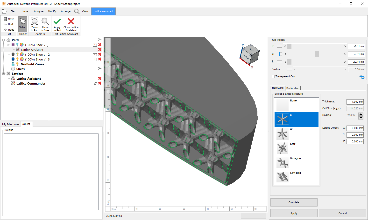 Netfabb Lattice Assistant combines Hollowing, Latticing and Perforations tools in one easy to access interface. Clip plane ‘Y’ is active to show the cross section of the part. Image via Autodesk
How to perform Boolean operations on an STL file?
Often designers have to make alterations to mesh files, such as .stl or .obj. Editing these files can be rather cumbersome, as there is only a triangular mesh left to deal with and no parametric data. As mentioned before, Netfabb has a mesh editing feature, which lets users manipulate triangles to edit the shape of a 3D model. This tool can be combined with the Boolean operation tool which adds to the design freedom offered by Netfabb.
A Boolean operation is a relation between two objects defined by Unify, Subtract, and Intersect actions. Unify combines two given objects, Subtract removes one from the other, Intersect gives the common remainder from two objects.
These operations are the foundation of parametric design or constructive solid geometry. Netfabb combines Boolean operations with mesh editing tools to expand the design capabilities of the software.
With the help of the Boolean operations, designers can add parts to an existing design or subtract from it (a mesh file). As was mentioned earlier, this is particularly helpful for creating hollow parts for SLA/DLP printing. Moreover, the subtraction operation can also be used to add holes to the 3D model, for the purposes described earlier.
Boolean operations are also useful in creating infills for hollow parts for SLA/DLP 3D printing. For example, a designer can model a customized lattice structure for a part. Using the Unify operation they can easily embed it as a modelled infill to a hollow part.
Moulds can be created by subtracting a model from a solid. This is easily done by adding a cube from Netfabb’s parametric part Library. The model to be moulded can easily be placed on the cube and subtracted.
Boolean operations can also be used to add more functionality to an existing part. For example, if a manufacturer wants to add a screw thread to a part for a stronger assembly but only has a mesh file of the original part, Boolean operations can help. A bolt can be created in Netfabb and subtracted from the target shape. To take account of tolerance and other mechanical issues, mesh editing tool can be used to offset the bolt.
In addition to this, Boolean operations are also good for combining designs. Designers can add logos or labels to existing .stl models, customized bases, or supports.
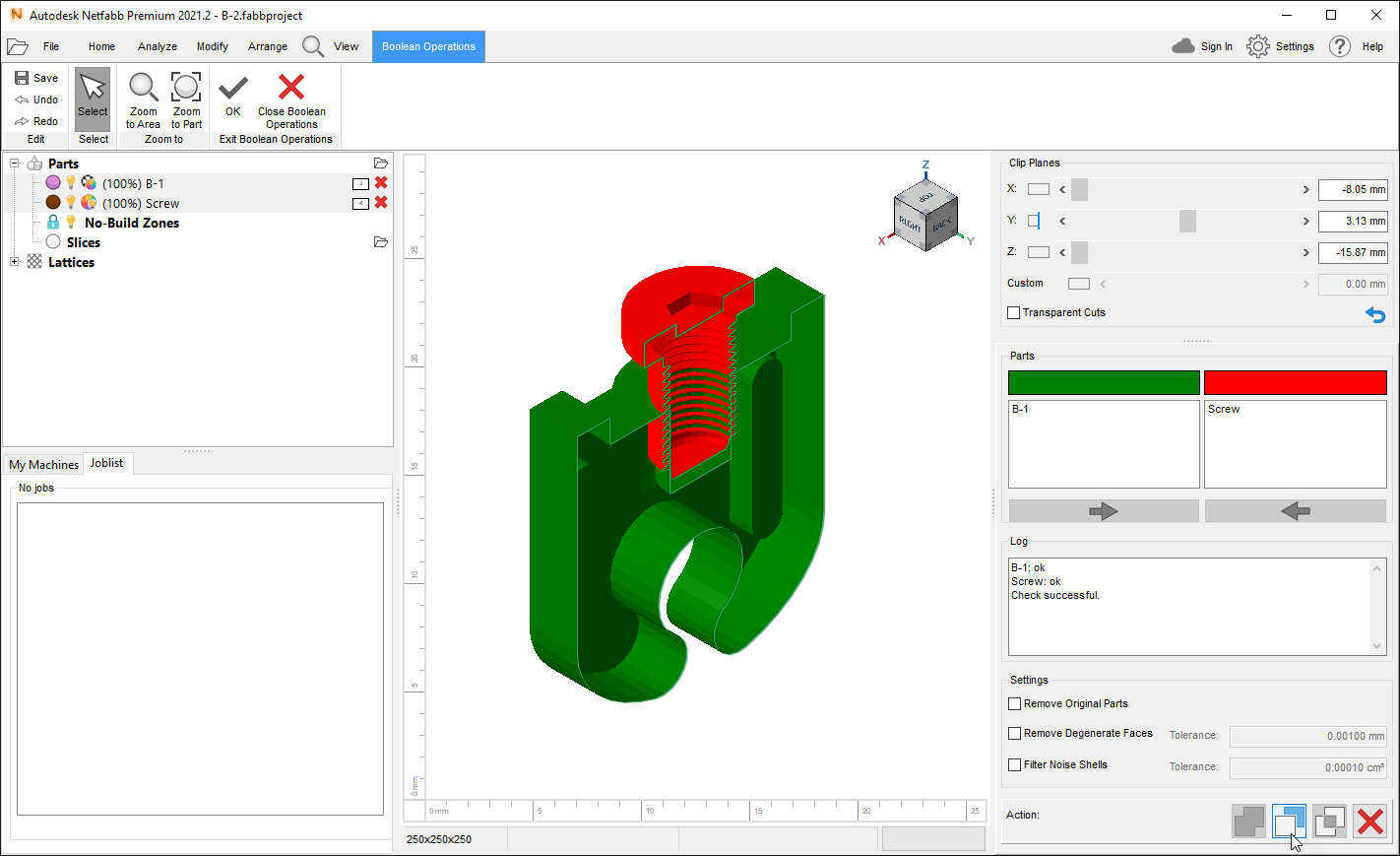 Performing the ‘Subtract’ action within the ‘Boolean Operation’ tab to remove the red part from the green part. Clip plane ‘Y’ is active to show the cross section of the parts. Image via Autodesk
How to compare two meshes in Netfabb?
As mentioned earlier, Netfabb can edit triangle meshes. Parts sometimes need to be rescaled, remeshed or smoothed. After such a process it is often necessary to compare the original and the edited part to measure deviations for tolerances. A comparison tool is indispensable for tolerance analysis and testing the overall quality of the 3D print.
A good mesh comparison tool can save labour, time and costs. For example, a business client may want modifications to the original model to make it more precise. In such a case only a mesh comparison tool can tell how much accuracy is viable and possible with mesh editing.
In Netfabb, using the ‘Compare’ function, which is accessible via the ‘Analyze’ tab, ‘Analysis’ panel, users can perform a comparative analysis between two triangle meshes. The comparison can be unidirectional or bidirectional on two similar models.
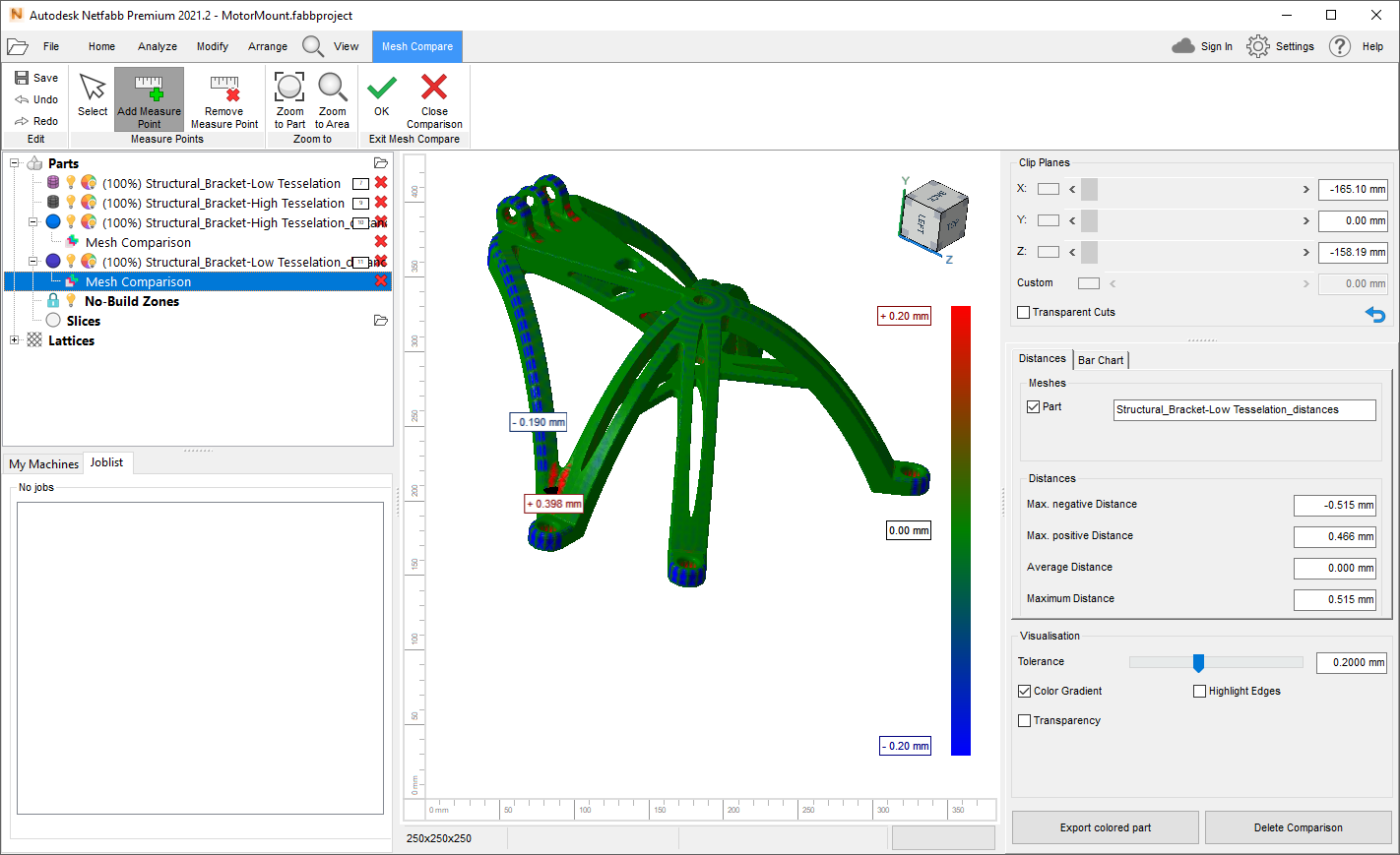
The ‘Mesh Compare’ module shows a detailed visual and numerical analysis of the altered mesh triangles. Data is represented with help of a colour gradient and statistic, such as the average distance of movement, maximum positive distance, and maximum negative distance.
The distance by which a triangle has moved towards or away from the center on a coordinate is represented by red or blue colours, on the deviation scale. The red colour shows that a triangle has moved away from the center, whereas blue represents the movement towards the center. Tolerance distance can be assigned a value to measure the permissible deviations from the original model. The green color on the model shows that the tolerance level is acceptable in a specific region.
Furthermore, a bar chart illustrates the distance a triangle has moved and how many triangles in the mesh have moved that distance. In addition to this, measure points can be added to calculate and label the deviations.
Finally, a mesh comparison report can be created using the ‘Generate Report’ function within the ‘Analyze’ tab. Simply choose the “netfabb_mesh_compare” item from the ‘Generate Report’ dialog and press the ‘Generate Report’ button. This will execute the automatic report creation action using the Open Office ODT template and output can be viewed with any software that can open .odt files including Microsoft Word. The report contains general measurements of the model and mesh comparison data. This can be particularly helpful for 3D printing service bureaus, who need to make reports for their clients before the manufacturing process.
 Mesh compare module in Netfabb. Image via Autodesk
How to take measures of an STL file
If files are not meticulously prepared for manufacturing prints might fail and 3D printing can prove to be an expensive manufacturing method. The modelling stage is as important as 3D printing. Therefore, having all the necessary tools for editing 3D meshes is important to ensure that the original model and 3D print corroborate each other. One such indispensable tool is the measurement analysis.
Measurement tools are not only essential for calculating dimensions of a model, but they are also necessary for repairing and editing 3D models. Moreover, these tools can become necessary to examine the printability of a model. For example, as wall thickness is crucial to determining printability of a 3D model, Netfabb has a special wall thickness measuring tool. In addition to this, Netfabb has various other measurement tools and functions which can calculate lengths, distance, and angles of surfaces and triangles in a mesh.
There are eight categories of measuring tools in Netfabb. These include point, edge, circle detection, 3-point circle, 4 point sphere, surface, wall thickness, and 3 point angles. The measurement tools in Netfabb use anchor points to make the calculations.
All these tools can be used with Netfabb’s feature detection and snap-on option, which makes it easier for the user to navigate through the mesh and attach anchor points to the model for calculation. With the help of feature detection users can peg the anchor points to primitive shapes, such as lines, edges circles, and planes. Snap on option makes the anchor point cling to the edges of the triangle. This option can be turned off or switched to ‘point on clip plane node’.
Measurements of all the distance and angles are displayed on a label. Users can label these comments for their own reference or for other designers. If the measurement labels clutter the view of the model, they can be dragged to move away from the part. This can be helpful if a designer has to share screenshots of the 3D model.
Furthermore, the measurement dialog in the module shows detailed statistics that can be of great help to engineers.
If there was no measurement tool, many of the editing operations in Netfabb would lack usability for professionals. Netfabb’s measurement tools compliment the editing features offered by the software, such as mesh editor and Boolean operators. For example, users can measure the distance between one point and a cut line, before making the edit. Moreover, detailed measurements can also help users align parts precisely.
Also, Netfabb can generate detailed drawings or blueprints that can be used to compare a 3D printed part with the original model. This can make the testing process more efficient.
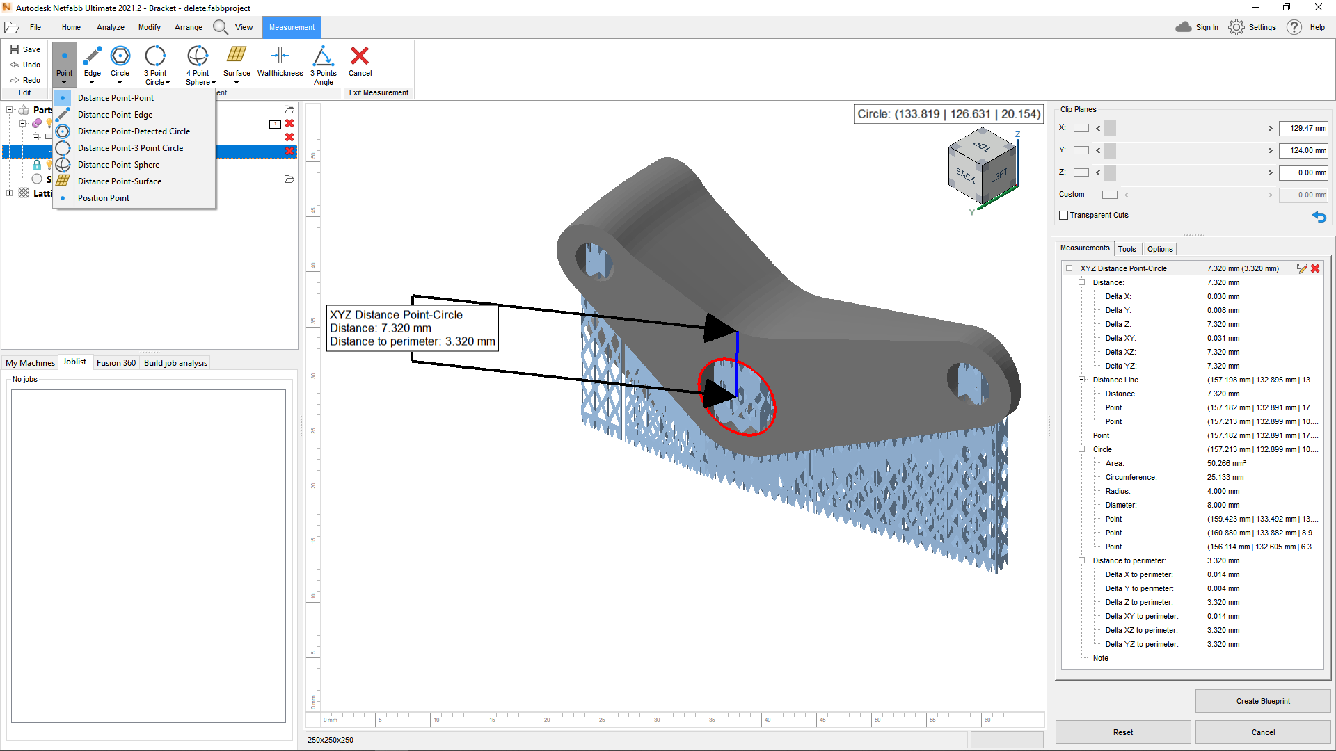 Performing measurements with Netfabb. Image via Autodesk
4 – Building and Slicing Strategies
In this chapter, we will talk about how Netfabb can be used to align parts on the build platform to make full use of the build volume and improve print quality. We will also learn how Netfabb Premium can create slices for DLP, and SLS, thus eliminating the need for using several separate slicing software.
How to align STL files on a build plate
The automatic orientation tool in Netfabb is a great help for exploring various positions of a part. However, it only works with single parts. Moreover, once a user has developed an intuition for orientation and support generation, manual arrangement might be preferred, in many cases, to improve the quality of the 3D print. For example, placing the 3D model in the middle of the build plate will ensure better quality it is generally known that FDM/FFF works best around the centre of the build area. Even SLS printers provide better temperature uniformity in the middle and back of the build chamber. Moreover, parts can be arranged to minimize support structure, or avoid supports on detailed portions of the model.
Netfabb has a selection of part arranging functions which can help in this regard. One among them is the ‘Align’ feature. A benefit of Netfabb’s ‘Align’ tool is that it lines up a part relative to another surface. With the align tool parts can be easily arranged in relation to each other, to the build plate or the X, Y, and Z axes.
Models can be placed parallel, anti-parallel, or perpendicular to each other. Parts can also be translated in relation to each other. To make such changes, the user has to select two surfaces on the parts which they want to align, and the alignment tool does the rest.
Having such extensive control over part arrangement can also assist with model editing using Boolean operations, as the alignment tool’s surface selection method is time-effective and more precise than manual handling.
Furthermore, the align tool can be combined with the ‘Move Parts’ tool to exploit the entire volume of the build plate. As mentioned earlier, Netfabb can help with automatic 2D packing. Part alignment tool can also assist with 2D packing as it lets the user orientate parts according to specific requirements. Moreover, a skilled user can also use the alignment tool to do manual 3D packing. However Netfabb Premium already includes several dedicated automatic 3D packing algorithms, so there is essentially no need to dive deeper in to that workaround in this guide.
As we know 3D printing forms an object by adding layers on top of each other. In the SLS method, layers are formed by sintering powdered material. The unsintered powder on the bed acts as support material for overhangs. Larger overhangs will have more powder support beneath them. Though the unsintered powder solves the support problem in SLS printing, it causes another. Each time the laser is fired onto the powder to form a layer, heat is transferred beneath the layer. So if a machine is printing large overhangs the powder beneath the first layer of the overhang will receive heat from the laser. This makes material particles stick under the bottom surface of the overhang layer, causing the surface to become rough.
The up/downskin analysis in Netfabb lets user visualize which parts of the model will have a rough surface due to overhangs. The up-downskin analysis and part alignment tool can be used in conjunction to find out the best orientation of a 3D model for SLS printing.
Users can define a critical angle threshold like 45°, and the up/downskin analysis will display which areas are above this threshold.
Furthermore, two of the characteristic problems associated with SLS printing are curling and warping. Curling refers to the deformation of the bottom layer, whereas, warping is the deformation of the whole due to shrinkage and residual stress.
Curling and warping occurs when a freshly sintered layer comes into contact with cold powder, which can happen when a new layer of material powder is laid on top of the sintered layer. A sudden temperature drop on the top surface of the layer causes it to shrink while the bottom part of the layer retains its high temperature. Other factors affecting curling and shrinkage include, the temperature of the walls of the chamber and the antioxidant gas inside the chamber.
It has been shown that in SLS printing curling and warping can be countered by orienting a part in certain ways. And Netfabb provides plenty of orientation options for the users. Furthermore, a Z compensation tool can also be used for quality control.
Furthermore, the ‘Support Volume’ calculation can also be added to the up/downskin analysis chart.
[GIF] Part alignment animation
How to slice an STL file for 3D printing
3D printers are only capable of reading two-dimensional data. Therefore, all 3D models need to be converted to two-dimensional data, which can be read by the target 3D printer. The translation of input from 3D to 2D is done using a slicing software, which ‘slices’ a 3D model into step-by-step layer pattern.
Netfabb combines all these phases into one software, and therefore only Netfabb Premium is needed for repairing, analyzing, and slicing a CAD model.
Netfabb Premium supports printers utilizing the following technologies: CDLP, DED, DLP, EBM, BAAM, MJF, SCA, SLA, SLM, SLS and UCVC. Some of these printers have proprietary software for slicing (Example: SLA with Formlabs), others utilize print prep software such as Netfabb for slice data (Example: BAAM with Cincinnati Inc.), yet others are able to utilize bot their own proprietary software and/or print prep software like Netfabb (Example: SLM with Renishaw)
The capabilities of Netfabb’s slicer are similar to other 3D printing slicer software available in the market. Netfabb’s slicer tool can define information such as layer thickness, the speed of the machine, and extrusion rate.
Furthermore, varying slicer settings can be used on a single model. This feature gives the users more freedom and control over the 3D printing process. Users can choose which part of the model they want to be more precise and which part needs to be printed at a higher speed.
Once the model is sliced it can be exported to a file compatible with the target 3D printer. Sliced files can also be exported as Image (Example: BMP or PNG) where each image represents a single layer, or Toolpath files (Example: CLI or MTT).
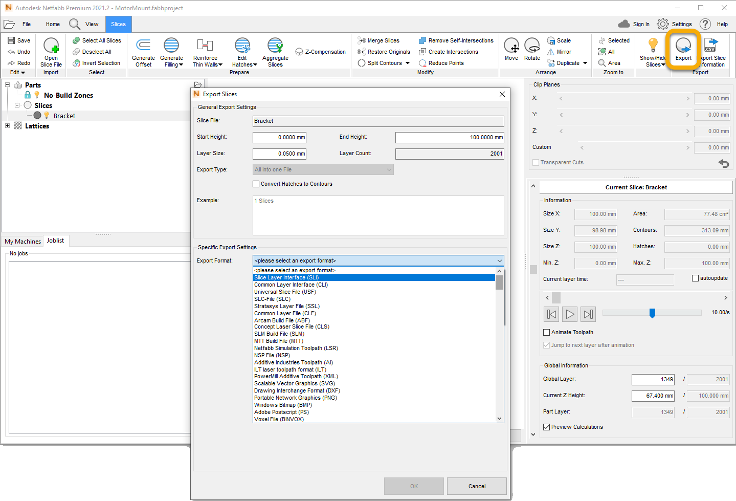 Various export file formats for Slice data within Netfabb. Image via Autodesk
In addition to slicing, users can also build supports in Netfabb. This can be done either manually or by running an automatic script. The ‘orient part’ function can run a search algorithm to find various orientations for the part. These orientations are ranked in accordance with the quantity of the support structure. For example, the top ranked orientation will be the one with the lowest volume of support. Users can also specify their own preferences to the orientation search algorithm. Once the favoured orientation of the model is selected, it can be exported as a 3D printable file.
Netfabb Premium can generate support structures for all 3D printing technologies which require supports.
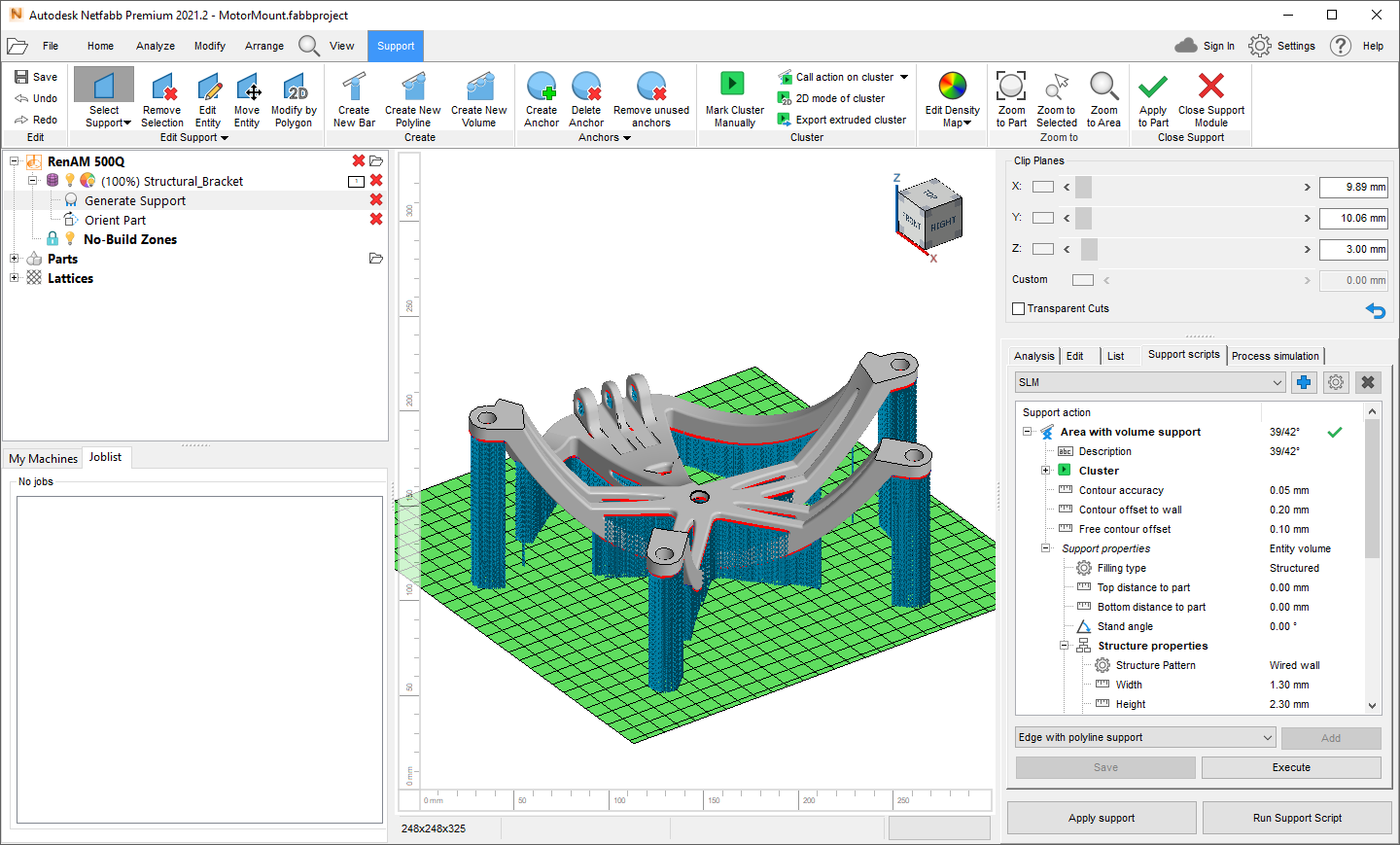 A part supported using the SLM Support Script within the Support Module of Netfabb. Image via Autodesk
How to slice for SLS 3D printers
In addition to slicing for DLP and BAAM, Netfabb can also make slice files for Selective Laser Sintering (SLS). SLS 3D printers use single or multiple lasers to melt metal powder in layers to fabricate a model. Slicing and creating the laser toolpath for such machines is more complicated than FDM/FFF desktop 3D printers.
To create a slice of a model for SLS, the model is first divided into contour layers, which are empty and need an infill pattern, also called hatch patterns.
Netfabb has standard hatch patterns used in laser printing, these include simple hatching, stripe hatching, quad islands, checkerboard hatching and radial hatching. These patterns can be customized by modifying various values such as the width of the stripe, the distance between stripes, the angle of the stripes, etc. For example, users can set a value for rotation per layer, which makes the pattern rotate at the given angle. Moreover, the start and stop points can be used to generate groups of slices with different settings. For example, from 0-10 mm simple hatching can be used, and from 11-20 mm quad islands.
Furthermore, Boolean operations can be applied to slices. This is particularly useful in SLS for creating custom infills. Users can import self-designed infills into Netfabb, slice them and apply an addition Boolean operation with the slices of the primary 3D model. This will generate an infill contour which can be filled with hatch patterns.
Moreover, hollowed parts can also be 3D printed with SLS. A slice can be offset from the contours to make a wall, which can be filled with hatch patterns. This leaves out the insides of the part empty. Like SLA printing, manufacturing a hollow part in SLS saves time and material.
All the different slices can be exported as a single file which can be loaded to an SLS 3D printing for manufacturing. Using the My Machines dialog users can set up SLS 3D printers such as the EOS P396. The 3D printer can be connected to Netfabb. The parameter settings are usually provided by the machine manufacturer. These settings include scanning strategy, such as the path of the laser, the speed and power of the laser. Scanning strategy is important to ensure best mechanical and thermal properties of the printed part.
For metal additive manufacturing systems, Netfabb has a collection of parameter settings from the manufacturer for different printing materials. And for such machines using the slicing module is not necessary, as 3D printer’s module in Netfabb can generate scanning strategy and infills.
[GIF] Animation of the slice
5 – Batch Printing
To maximise the opportunity of 3D printing, efficient workflows are important. Therefore, manufacturing multiple parts in one print run saves time and money. This is important for businesses and institutes as it may be to necessary 3D print 10 or 100 tests with varying print settings. Furthemore, reports can be generated for comparison and data purposes, or shared with customers.
In this chapter, we will learn about Netfabb’s tools for batch printing and reporting.
Batch printing (labelling)
Batch 3D printing can give businesses an edge over the competition. To manufacture a large quantity of parts, it is important to utilise the full potential of a 3D printer. This means, among other things, exploiting the volume of the build plate to 3D print multiple models in one go.
Netfabb includes several methods for packing or nesting parts, which can automatically arrange models in a printer. Both the “2D packing” and the “Simple Outbox packing” algorithms can nest parts on the X and Y axis of the build plate. Users can also further arrange parts manually with the help of move and rotate tools. Parts can also be aligned in relation to each other. Two parts can either be placed perpendicular or parallel to each other or they can be stacked on top of each other.
Netfabb also has 3D packing functionality which arranges 3D models along XY and Z axis. And it is often used with SLS and MJF technology, as they do not require support structures. For packing parts in 3D there are several methods one can use. User can choose from the “Simple outbox packer” with the Packing dimensions “in 3D” option enabled, or 3D Packing – Scanline, MonteCarlo, Gravity, or last but not least Size Sorting algorithms.
Batch printing in Netfabb is complimented by the labelling feature. With the help of labelling, multiple parts can be branded with an identifier using a text or logo. This can make the post manufacturing operations efficient. For example, a dentist could create multiple dental models for patients using the 2D packing functions in Netfabb. In such a case, it would be convenient to have some sort of an identifier for each dental model belonging to different patients.
Furthermore, the labelling feature can also be helpful in 3D printing a multiple component model. Each part can be named to facilitate the assembly of the model after manufacturing.
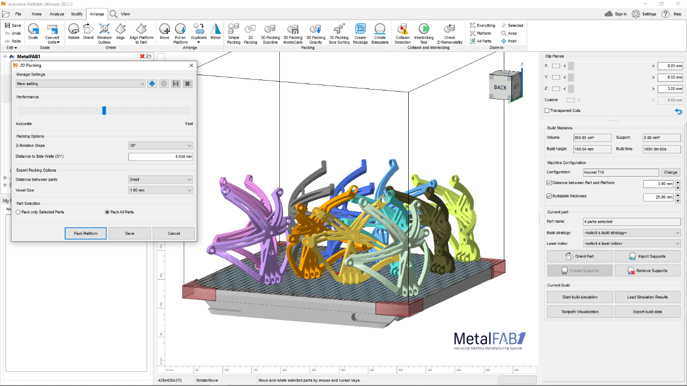 2D Packing makes the most of X and Y axes of the build plate. Image via Netfabb
How to generate report for 3D printing
Netfabb’s main audience is research institutes, businesses utilizing 3D printing in a production setting, such as printing bureaus as well as organizations that are looking to increase their 3D printing design and manufacturing productivity. For such industries, sharing detailed reports is an essential part of the AM workflow.
Netfabb can produces a lot of useful data, which can be exported to an .odt, .xls, or .pdf format. The default report templates in Netfabb includes mesh compare, part analysis, platform views, and quotations.
In addition to these, users can design custom report templates. These can be made in software called Pentaho Report Designer. The report designer by Pentaho is not part of Netfabb. It is a separate software used to create report templates. Pentaho generates the templates in a .prpt file format.
As 3D printing businesses have a variety of clients, custom data reports can be extremely useful in addressing specific needs of clients. For example, if a part is not printable due to design problems, businesses can display and share relevant values in the report, such as the number of triangles, number of holes, number of shells etc. As .odt and .xls files are editable, they can be modified for clients.
To create a custom report, a list of Field tags must be added to the report template. Netfabb uses these tags to communicate with the .prpt file and export the values to an .odt, .pdf or .xls file. The Field tags can be used to add custom fields in the Pentaho report. The tags include NETFABB_ENGINE_BUILDTIME for the build time, NETFABB_PART_SUPPORTVOLUME for support volume estimate and NETFABB_PARTCOUNT for the number of parts on the platform, among many others.
The .prpt file must be placed in the Netfabb’s ‘Report’ folder otherwise the ‘Generate Report’ dialog will not show the customized report.
Furthermore, .odt. report files in the Netfabb’s Reports folder can be edited to add header and footer and include the name of the company. These report generation feature of Netfabb can be helpful to small businesses. Since report templates do not need to be filled manually and individually each time, it could save a business time and labour.
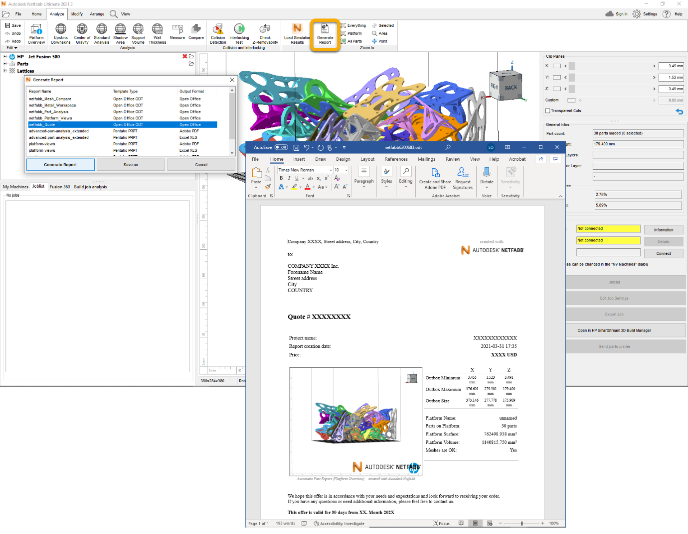 Generating an automated report in Netfabb. Image via Autodesk