This post is the last of a series of three by Spencer Wright, a strategist at Undercurrent, on the state of the metal 3D printing process. Read parts one and two for an overview of the project and background information on the metal 3D printing process.
Support structures & Iteration
While I was in Cincinnati, I visited MicroTek Finishing — a major player in the metal 3D printing world. While there, I spoke with Tim Bell, who related an anecdote about his time at Morris Technologies, the aerospace 3D printing giant that was acquired by GE in 2012. Tim was a product development leader at Morris, and he talked of a large bin that they had in their shop. It was called the “Bin of Broken Dreams”, and into it went an endless stream of failed parts.
My part has now been printed in six different build configurations. We (and, by we, I mean Dave Bartosik, whose creativity and enthusiasm for getting the build to work was inspiring) added solid supports in a number of places, chasing built-in stresses around the part with each iteration. The latest prototype, although nonfunctional, is nevertheless a big improvement on the earlier builds — and the process has taught us a lot about the idiosyncrasies of my design.
To begin, Dave let Materialise Magics (the industry standard for support structure generation software) do its thing with no manual intervention. Magics generates mesh support structures, which are scanned every other layer of powder (solid regions of the part are scanned every single layer). As a result, they’re very easy to chip off the part — but don’t have the same strength that solid supports do. As internal stresses proved to be an issue, Dave added solid supports to keep the part undistorted and tied to the build platform.
Build 1
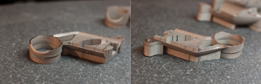
In this build, the part is laid on its side and supported only by mesh supports. The build failed at only 15.6mm in the z-direction, when the recoater jammed on the saddle clamp end of the part, which had lifted from the build platform.
Build 2
Here, the seatpost clamp cylinder is firmly fastened to the build plate. But the stresses just concentrated on the other end of the part, pulling the bolt boss and some of the front edge off of the platform at a height of 22.7mm.
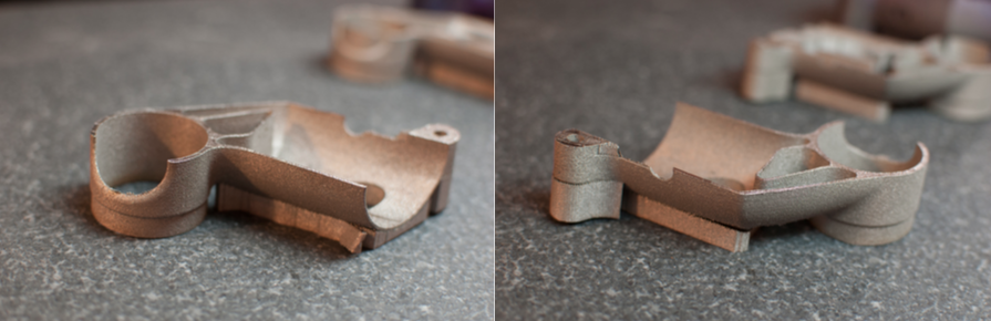
Build 3
Both ends of the part — the saddle clamp and the bolt boss — are firmly anchored to the build platform. But this created a complex bending moment, pulling the center of the part upwards; the build failed at 22mm.
Build 4
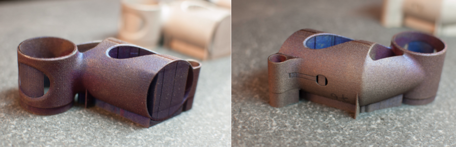
Here, we’ve got solid supports on both the saddle clamp cylinder and the bolt boss, and added an additional solid rib to the middle of the part, tying it down there. This is the first build that completed; all of the others had failed midway through. We’re clearly getting closer, but the bottom of the part has distorted, pulling in and looking like a big “D”.
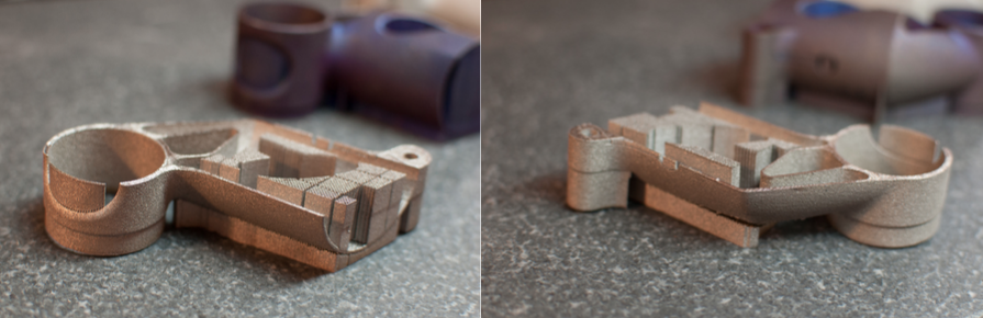
Build 5
To prevent the bottom of the part from distorting like in Build 4, we added a second solid rib. It helped, but only below the centerline of the cylinder; above that, the wall still pulled in.
Build 6
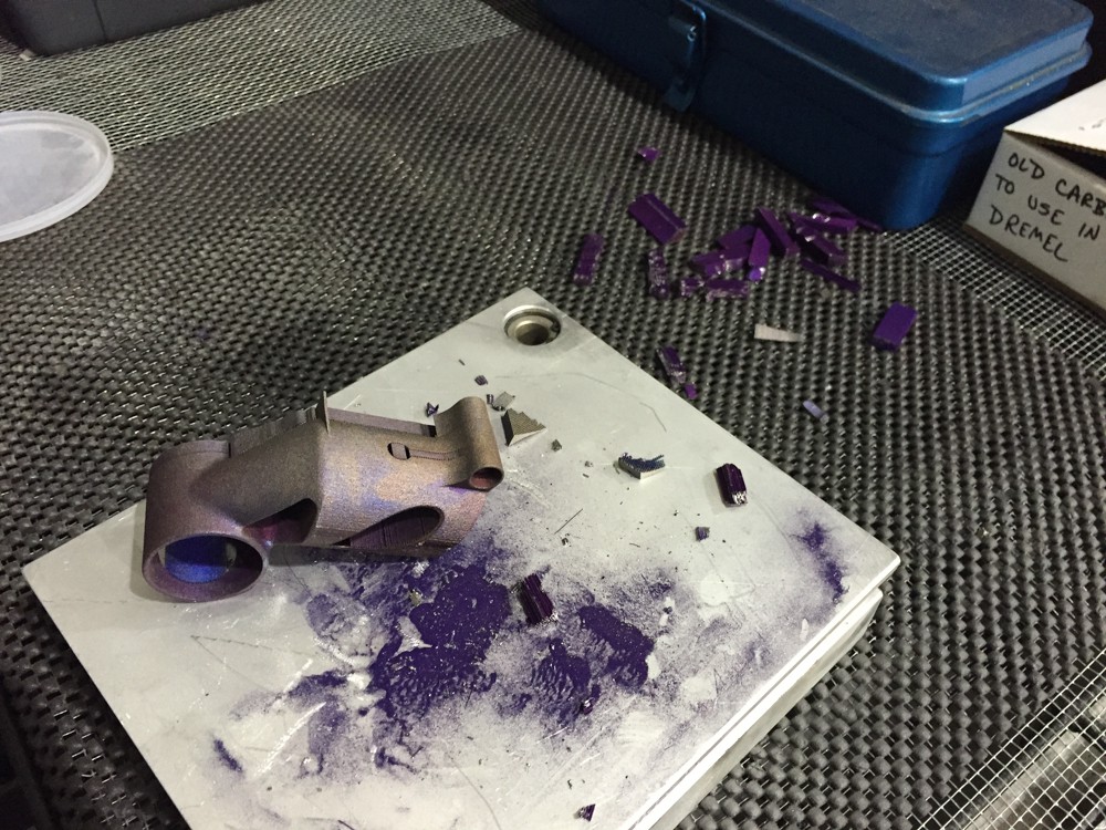
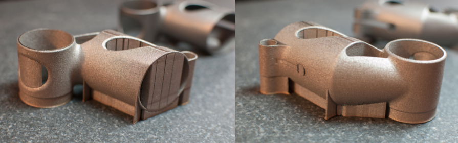
Build 6 finally produced a part that’s generally round and complete. This was achieved by extending the lower rib up the side of the part, giving external support to the entire bottom edge of the seatmast clamp cylinder. But although the top and bottom of the seatmast clamp are both basically round, the internal stresses still needed to go somewhere — and ended up bulging out the middle of the tube instead.
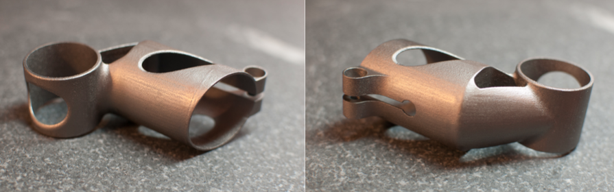
Throughout each of these builds, three things have remained consistent. First, the surface finish on the exterior of the part leaves much to be desired; it will definitely need to be finished in a separate step. Second, the surfaces that needed to be EDM cut from their solid supports (the saddle clamp and the bolt boss) are irregular, and will need to be smoothed into the rest of the part. Third, the internal diameters will almost definitely need to be post-processed by machining or EDM — even the saddle clamp, which, overall, had a passable surface finish, was undersized by .020″ — about four times the desired variance.
The net effect is that after six build iterations — each of which took almost two full days to set up, build, stress-relieve, and cut off of the build plate — we still don’t have a functional prototype to test.
Takeaways
What to take away from this? Well, prototyping is hard — but everyone knows that. My primary observations have more to do with the state of the industrial marketplace, and the maturity of metal 3D printing processes, than with the fact that we’ve now put six parts into our own bin of broken dreams.
File processing
As with consumer 3D printing, industrial 3D printers work exclusively from STL files. This produces a total break in the design-to-manufacture process. When I export an STL to send to a manufacturer, all of the underlying feature data is lost; all that’s left is a shape. This is drastically different from the conventional manufacturing world, where parts are regularly built directly from underlying design files.
Tolerances
For the vast majority of machined parts, any single dimension is expected to be accurate to within .005″, regardless of size (in other words, a quarter-inch hole should be between .245″ and .255″, and a one-inch hole should be between .995″ and 1.005″). For a relatively small cost, designers can specify even tighter tolerances, and the means of achieving them are predictable and not overly complicated. But with additive, tolerances accumulate across the part at a rate .005″ for every inch of distance. That’s fine if you’re building a one-inch part (whose dimensions will be between .995″ and 1.005″), but larger parts can be problematic; a ten-inch part will be between 9.950″ and 10.050″ — a decidedly generous tolerance. Moreover, these tolerances don’t always stick; many of our early prototypes didn’t come close to meeting them. And, when a part prints out of tolerance, the way to fix the problem is essentially to fiddle with the underlying design and then build it again.
Intellectual Property
Across the metal 3D printing industry, a stream of contract manufacturers told me the same thing. DMLS build processing is hard, they say. And the only way to maintain a competitive edge is to invest countless time and money into R&D — and then guard institutional knowledge vigilantly. On many occasions this is referred to as intellectual property, but the truth is that it’s closer to expertise; what’s being developed is craftsmanship, not patentable tools or methods. But whatever the name, the effect to designers is stifling. Regardless of manufacturing method, the design-to-manufacture process benefits from transparency; if a build fails, then I, as a designer, want to know the reason — and adjust my underlying design accordingly. Until the additive supply chain opens up to sharing its experience in the design-to-manufacture process, new DMLS products will be few and far between.
Undistributed Manufacturing
Today, 3D printing metal parts via a distributed supply chain is a myth, full stop. And, while I’m as excited about that vision as the next guy, distributed manufacturing will continue to be a pipe dream for the foreseeable future. A distributed manufacturing ecosystem can only exist once there’s a robust network of suppliers capable of making parts repeatably. And, while it’s my sincere feeling that the most hardworking, intelligent, and visionary people in manufacturing today are working in 3D printing, there simply isn’t currently a rich network of DMLS suppliers. For instance, the closest DMLS-equipped shop to New York City is a 200+ mile drive away. Meanwhile, MFG.com lists 68 machine shops within a 150-mile radius. If distributed 3D printing is to become a reality, the install base must increase by orders of magnitude — and the reliability and repeatability of the processes must improve dramatically as well.
In-Process Monitoring
In conventional manufacturing, parts are checked between operations to ensure that critical dimensions will be met. But the current generation of industrial 3D printers have little in the way of in-process monitoring, with the result that distortion isn’t detected until the build fails altogether. Although there are hints that this may be changing (B6 Sigma has announced some ambitious plans recently, and a lot of primary research is being done on the subject), the fact remains that until we’re measuring and analyzing the factors (thermal gradient, sound, vibration, etc.) that indicate build failure before it happens, trial-and-error will be the only way prototypes are developed.
The Process Chain
3D printing is very, very good for certain things. But it is not a one-stop process. For now and the foreseeable future, additive manufacturing will be a poor method for creating a number of important mechanical features, including many aspects of fastening and articulation. In addition, the surface quality of 3D printed parts will be unacceptable for anything requiring tailored aerodynamic features, and will be similarly poor for products whose fit and finish are of high value for aesthetic reasons. This is not to say that those aspects won’t improve; they will. But, while I expect additive manufacturing to be an important part of the way parts are produced in the future, it’ll be a long time before it’s used to produce a wide range of products. And for those products which are well suited for 3D printing, their total manufacturing process chain will include subtractive tools (machining, honing, polishing, etc.) for the foreseeable future.
Next steps
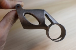
My part has come a long way. Just having a physical prototype in hand makes a huge difference in understanding its benefits and drawbacks, and I continue to believe that with continued research and prototype development, I will find a way to make it commercially viable and attractive to high end cyclists.
But there’s much work to do. Moving forward, I see three primary directions to explore:
Keep the current build orientation, and continue to iterate on support structures as necessary.
At this point, it’s clear that we need to rethink the way we’ve been mitigating internal stresses. The external ribs are working somewhat, but, even if we can add enough of them to make the build work, they leave ugly marks on the outside surface which require additional post-processing. Instead, I plan to experiment with reinforcing the inner diameter of the seatmast clamp cylinder. One thought is to create an internal lattice (like those that Frustum’s software creates), which would provide rigidity during the build and then be removed via machining afterwards.
Change the build orientation
Turning the part so that it’s upside-down on the build platform — with the seatmast clamp on the top — will offer significant advantages. The saddle clamp already has a thicker wall than the seatmast clamp, and is likely to resist distortion more easily. And, with the seatmast clamp oriented in the z-axis, it’ll be in much less danger of distortion.
Try EBM
The electron beam melting process preheats the entire build platform to just under the melting point of titanium, and so generates much lower thermal gradients — and, as a result, less internal stress — than DMLS. EBM also generally requires fewer support structures, which is helpful for part cleanup. However, the surface quality and minimum feature size of EBM is significantly worse than DMLS, so EBM would probably require a longer overall process chain, with more material removal than DMLS would.
Regardless, I’ll be continuing this work over the coming months. These technologies are changing rapidly, and any ambitious product designer would be wise to pay close attention to their development. And only by experimenting with actual parts can anyone hope to keep up.
I believe that functional, engineered consumer products made by additive manufacturing are an inevitability. But as a product manager today, the viability of metal 3D printing is totally opaque, and that will only change by careful study of the efficiencies (and inefficiencies) of the additive manufacturing toolchain.
Join me in working to make that a reality.
Thanks
First, thanks to Dustin Lindley (of UCRI) and Dave Bartosik (of DRT — Morris), without whom all the cool stuff described above would have never happened. Thanks also to Greg Morris (who originally connected me with Dustin, Dave, and Chuck Hansford at DRT), to Clay Jones and Jordan Husney for their creative inspiration and infectious enthusiasm throughout the process, and to Clay Jones and Mike DiGiulio for reading early drafts.
Lastly, thanks to Undercurrent, which is providing critical funding for this project — and which I am proud to call home.