
A team of six international scientists have developed a new computational framework for the multi-axis, non-planar 3D printing of polymer parts.
The FFF-based technique works by aligning filaments along the direction in which they experience the greatest stress, alleviating ‘weak points’ and increasing the overall strength of the part. The work has garnered some very promising results so far, yielding up to 6.35x increases in part strengths when compared to conventional planar FFF printing.
Anisotropy in 3D printed parts
As advanced as 3D printing is, there is still the widespread issue of anisotropy. The mechanical properties of 3D printed parts tend to vary depending on the direction or axis a force is being applied. This effect is particularly apparent in FFF printed parts due to the notoriously weak inter-layer bonding in the Z-axis. As a result, the process is often considered insufficient for industrial or production applications that require high stress resistance.
As it stands, there are a number of methods that can be employed to improve the mechanical properties of polymer parts. This includes heat and chemical treatments, variations in the infill percentage and structure, and even redesigning the geometry of the part. Taking a whole new approach, the research team utilized the anisotropy phenomenon itself to control and improve the strength of parts fabricated via FFF.
The multi-axis 3D printing framework
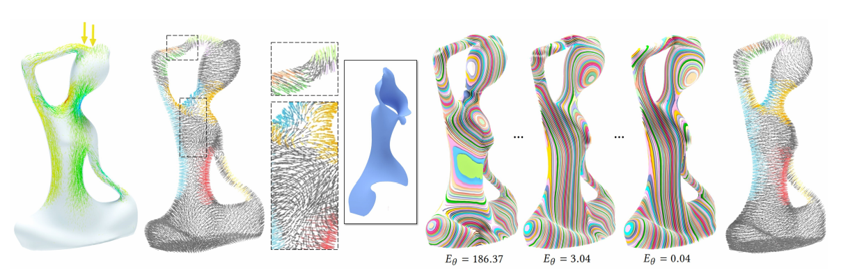
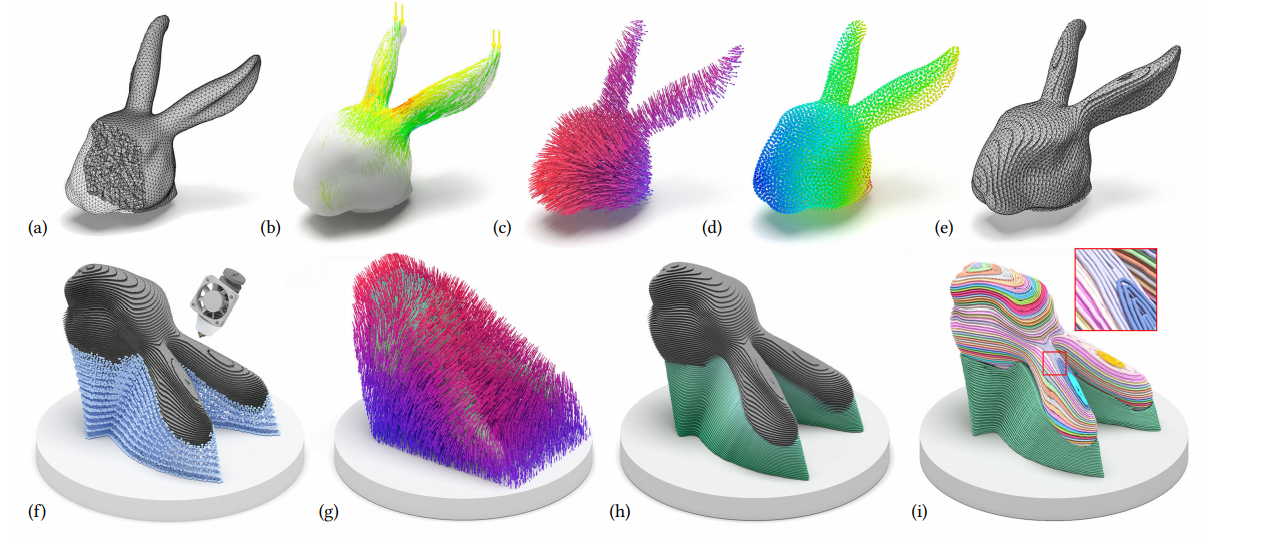
The framework, at its core, works by breaking down a 3D model into a sequence of “strength-aware” and collision-free curved working surfaces, like abstract slices of a very complex, convoluted cake. These curved working surfaces act as an alternative to the conventional layers found in planar 3D printing, but allow for more dynamic variations in the printhead’s toolpath.
First, an optimized governing field was computed, from which the individual working surfaces could be extracted. According to the researchers, the computational process was “naturally inherited from finite element analysis”, which is used by engineers to simulate the stress distributions in parts under loading. The resultant mesh was composed of a set of tetrahedrals.
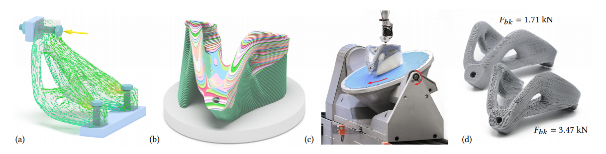
Based on the governing field (which takes into account the stress distribution in the part), the support structures for overhangs and bridges were extrapolated, and the individual curved layers were generated. Finally, the toolpaths were optimized to align with the weakest axis in each of the curved surfaces, maximizing the strength of the part in every direction possible.
When it came time to test the framework, a set of prototypes were FFF printed and put through their paces with tensile and compression tests in a laboratory. The researchers describe the experimental test results as “encouraging”, with typical strength increases in the region of 1.42x – 6.35x when compared to conventional planar 3D printing.
Further details of the study can be found in the paper titled ‘Reinforced FDM: Multi-Axis Filament Alignment with Controlled Anisotropic Strength’. It is co-authored by Guoxin Fang, Tianyu Zhang, Sikai Zhong, et al.
Computational methods have been used extensively to detect flaws, improve mechanical properties, and diagnose failures in 3D printed parts, with some projects taking it a step further and utilizing machine learning. Michigan Technological University’s Dr. Joshua Pearce recently developed an open source, computer vision-based software algorithm capable of print failure detection and correction. The process leverages just a single webcam watching over the build plate, tracking any printing errors that appear on the part during the fabrication process.
Elsewhere, at Argonne National Laboratory and Texas A&M University, researchers have developed an innovative new approach to defect detection utilizing real time temperature data. Using machine learning algorithms, the scientists were able to make correlative links between thermal history and the formation of subsurface defects during the laser powder bed fusion process. The relationship was then extrapolated to predict upcoming defects just based on the temperature profiles in the build chamber.
The 4th annual 3D Printing Industry Awards are coming up in November 2020 and we need a trophy. To be in with a chance of winning a brand new Craftbot Flow IDEX XL 3D printer, enter the MyMiniFactory trophy design competition here. We’re happy to accept submissions until the 30th of September 2020.
Subscribe to the 3D Printing Industry newsletter for the latest news in additive manufacturing. You can also stay connected by following us on Twitter and liking us on Facebook.
Looking for a career in additive manufacturing? Visit 3D Printing Jobs for a selection of roles in the industry.
Featured image shows the process by which a model is broken down and reconstructed with curved layers for added part strength. Image via Wayne State University.