
There’s now less than a week to go before we close submissions to the 2019 3D Printing Industry Awards Trophy Design Challenge in collaboration with Protolabs. This year, we designers can stretch their imaginations by designing a two-part object to be made using both Multi Jet Fusion (MFJ) and stereolithography (SLA) 3D printing processes.
For those of you who are still putting the finishing touches to your entries, we asked Joe Cretella, an Application Engineer at Protolabs in North Carolina, for some tips on how to design for MJF and SLA technologies.
The final deadline for entries is May 1, 2019. Looking to submit your design? Use the tag #3DPIAwards on Twitter, and post your work here. The winner will be selected before the official awards presentation on June 6, 2019 and, in addition to their design being created, will earn themselves an Ultimaker 3 3D printer. We wish all participants the very best of luck!

Reliable 3D printing on an industrial scale
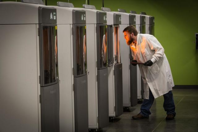
The Protolabs facility in Raleigh, North Carolina, spans approximately 77,000 square feet and is responsible for handling all 3D printing requests in North America. For this service, the company has over one-hundred 3D printign systems, offering Polyjet, Selective Laser Sintering (SLS), Direct Metal Laser Sintering (DMLS) and of course SLA and MJF. Around half of these machines use SLA technology, which is provided by 3D Systems on the Viper 6000 and 8000 series machines. There are around seven HP MJF machines at the facility, and these run 24/7. “We’ve got a lot of capacity within that technology,” comments Cretella, ” And we’re able to turn builds around very quickly.”
In addition the sheer scale of 3D printing capabilities at Protolabs, one unique aspect of the company is that it develops its own build parameters for the machines to achieve the best possible results. In particular, Cretella says, “We are really able to accurately control the stereolithography process, and achieve incredibly fine detail within parts. The results we get are very consistent, and we are able to attain very tight tolerances within that technology.”
As a newer technology, Protolabs’ specific parameters for MJF are still in development. However, its similarities with SLS has enabled the team to leverage their existing capabilities and knowledge to build MJF parts very well. “At this point, we’re still using the standard parameters,” Cretella adds, “Leveraging a lot of the knowledge we’ve gained from SLS and how we orient parts, how we nest parts within a build, things like that, that’s how we’re proving that process.”
SLA design tips
With 3D printers at home, the majority of designers will be familiar with the design rules of FDM/FFF technologies – 45° degree overhangs, the scale of features, orientation etc. Broadly speaking, when moving to design for SLA, the guidelines are very similar. “You have a platform and the part is going to be anchored to that platform [in some way]” Cretella explains. In this respect, considerations surrounding support structures still apply, i.e. fine features of your object should avoid support areas, and direct contact with the build platform.
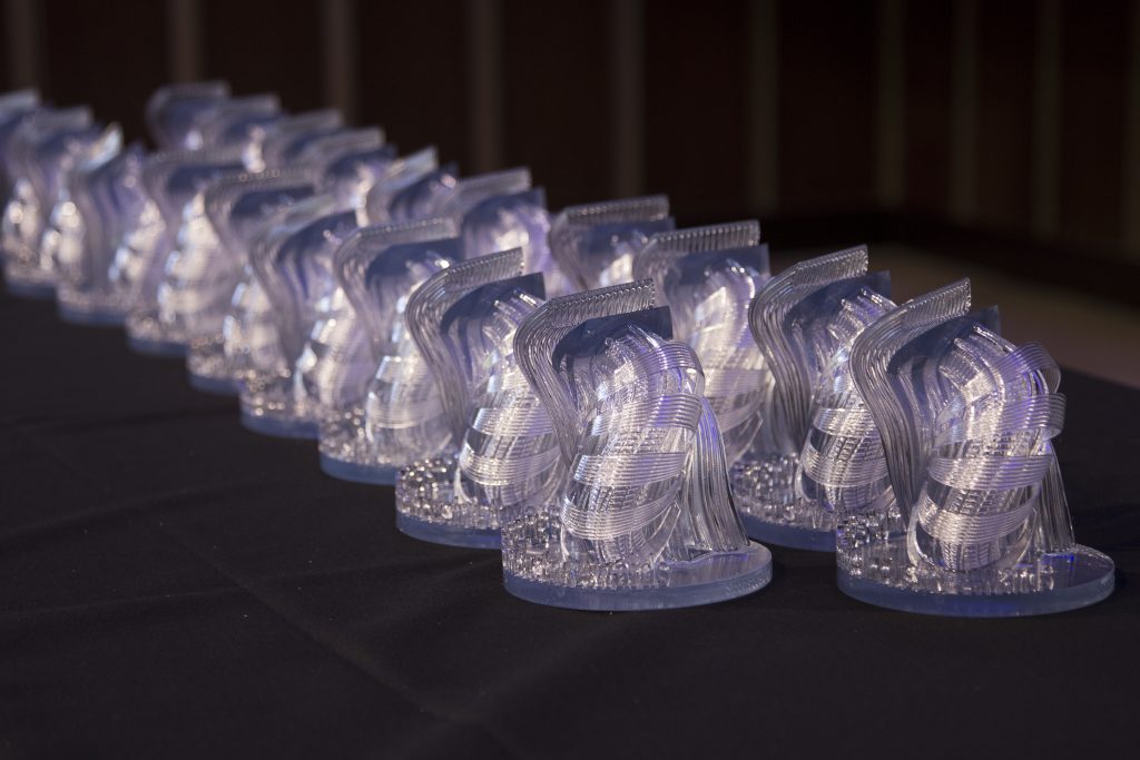
The main difference with SLA is that you will be able to achieve much greater detail that in FFF prints. “When looking at SLA, I think about finer feature detail, tighter tolerances, prints that are really nice cosmetically, parts that are going to be used for fit testing, a little bit of functionality testing – being able to produce really intricate designs.”
MJF design tips
Contrasting SLA and FFF, MJF does not require the addition of support material, and so in some ways design for this technology is much more flexible.
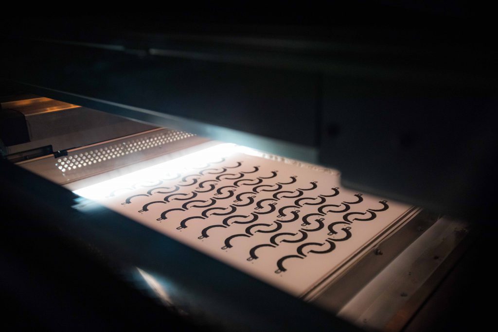
To make the most of MJF capabilities however, Cretella says you’re looking at “more industrial use case applications” such as equipment housings or tools, “Components that are going to see real use – they’re going to be used in harsh environments, outdoors, things like that.” Generally, in comparison to SLA and FDM/FFF parts, Cretella considers MJF components to be “durable, larger, chunkier, and able to take stress.”
“It is very nice to be able to build complex parts within MJF, because of that lack of support,” Cretella adds, “but you do have to keep in mind how we’re going to remove the powder.”
“With channels or harder to reach areas, you just want to make sure that we have a of line of sight, so we’re able to get compressed air or a tool down in there to remove some of that powder.”
Combining MJF and SLA in a single object
As requested in the design guidelines, the 2019 3D Printing Industry Award Trophy must combine parts made using both MJF and SLA technology.
“With 3D printing, there’s an opportunity to combine those those components in a really unique way,” say Cretella. Some suggestions include fitting parts together with pins, through press fitting, or even interlocking the parts.
Submit your designs for the 2019 3D Printing Industry Awards Trophy Design Challenge now. Entries close on May 1, 2019, and are open to all abilities.
Vote now in 2019 3D Printing Industry Awards. For more information on the latest trends in additive manufacturing subscribe to the 3D Printing Industry newsletter and follow us Facebook and Twitter.
Featured image shows the 2019 3D Printing Industry Awards Trophy Design Challenge graphic