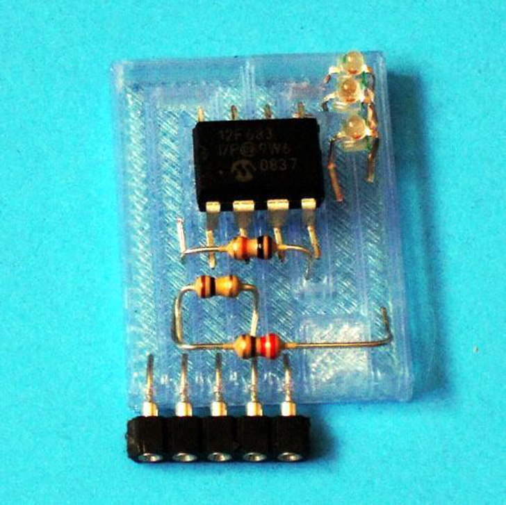
3D printed projects often include electrical components, so many hobbyists rely upon using breadboards in lieu of creating custom circuit boards. However, Instructables user mikey77 has devised a way to 3D print custom circuit boards that doesn’t require any soldering.
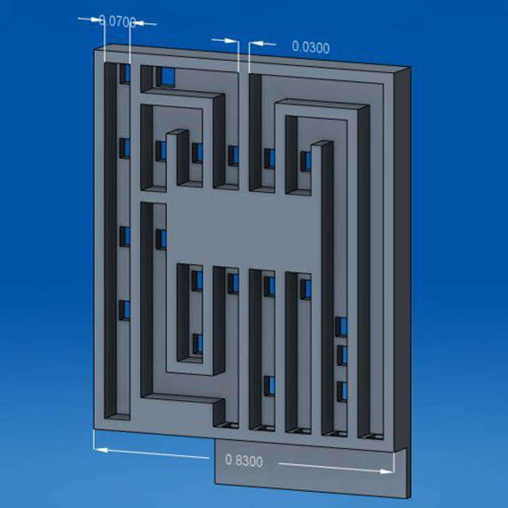
Mikey began by modeling the circuit board in CAD, and then added holes and cutouts for the leads and trace channels. The board was designed to conform to a 1/16” standard thickness for through-hole circuit boards. Once the components are placed on the board, the leads are then bent over to secure them.
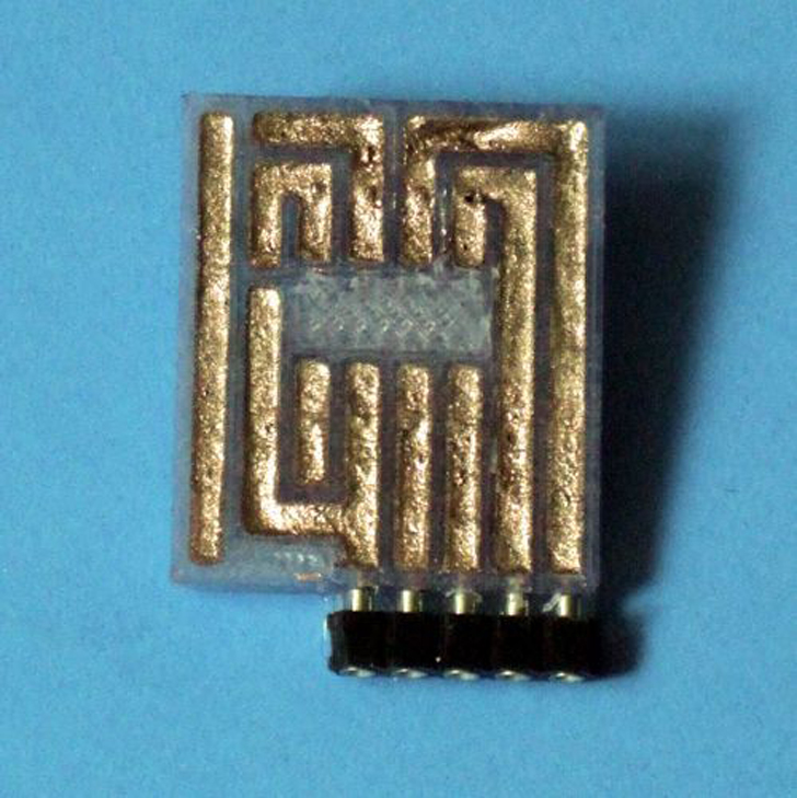
The trace channels are then filled with a conductive material to form an electrical connection. There are a few types of conductive materials to choose from. The author recommends a conductive CuPro-Cote paint as the easiest and most affordable option. Silver epoxy is a viable, but more costly alternative. If neither option sounds enticing, then Mikey provides instructions for how to make your own conductive glue/paint. However, he warns that the resistance of homemade conductive paint is significantly greater than that of commercial products. Even commercial glue/paint won’t compare to Voxel8’s low-resistance conductive ink, but it’s suitable for small hobby applications.
His design process can be applied to nearly any custom design, but there are a few characteristic dimensions that should remain the same regardless. For example, all traces should be 0.07” wide, and trace walls should have a minimum width of 0.03”. This helps to ensure that there’s an adequate amount of conductive material while preventing accidental short circuits.
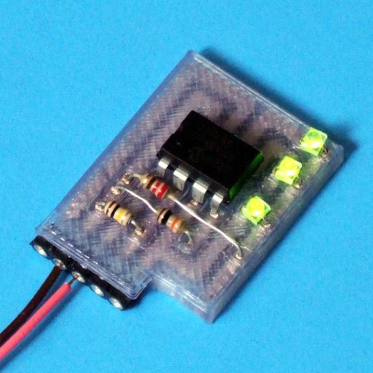
A circuit designed to sequentially blink three LED’s by using a Picaxe microcontroller is referenced as the Instructable’s example. All of the code and CAD files are provided for those who’d like to replicate it.


