Improving additive manufacturing (AM) processes to enhance quality, reliability, and yield is crucial for broader adoption. One key metric for evaluating process reliability is the yield rate, which measures the percentage of successful builds out of a given number of attempts. The yield rate, in turn, feeds into the final unit part cost.
As we know, part cost is the adoption hurdle potential applications can struggle to overcome.
In this guest article, David Maass examines how in situ inspection can hasten AM adoption and how to achieve it. Want to share your insights with our readers? Get in touch.
In Situ Inspection for Additive Manufacturing: How and Why?
In-process inspection, AKA in situ inspection, involves scrutinizing each layer during or immediately after fabrication and can improve AM yield. In-process inspection starts with anomaly detection, identifying deviation from the desired outcome. Detection includes specifying the location of anomalies in terms of the X, Y, and Z coordinates within the build volume. Anomaly classification is essential, categorizing anomalies based on their type, for example, lack of fusion, rough surface, or spatter particles. Finally, the magnitude of anomalies is measured against a threshold, classifying them as flaws or not.
This comprehensive inspection process enables a deeper understanding of how, where, and why flaws occur, facilitating targeted improvements to enhance yield and overall part quality.
In-process inspection plays a vital role in both the development (nonrecurring) and recurring production phases of AM operations, offering several benefits.
During the development of the build procedure, in-process inspection helps identify quality issues within the part. This information guides sequential adjustments to the build procedure, such as optimizing part orientation, support structures, and process variables like laser power, scan speed, and scan pattern. This iterative process aims to eliminate quality problems and refine the build plan until it consistently produces acceptable parts without significant flaws. While this phase is non-recurring (a one-time use of in-process inspection until a qualified build plan is established) it can significantly reduce the time and cost of this step compared with relying upon DfAM rules and human intuition.
In recurring serial production, in-process inspection identifies regions of parts that may contain flaws. Although the qualified build procedure described above is designed to minimize flaws, certain stochastic elements of the AM process, such as the formation of spatter particles or plasma plumes, can still occur randomly and lead to flaws. In-process inspection enables the detection and assessment of these issues as they arise, allowing for timely intervention to maintain quality standards.
Not all detected anomalies will reach the defined flaw threshold or impact part quality. Those anomalies are typically recorded for documentation purposes but may not require immediate action or notification to the operator. This distinction allows for efficient use of resources, focusing attention on critical issues while minimizing disruptions to production processes.
Anomaly Detected: Now What?
Identifying “fatal” flaws during the additive manufacturing (AM) process is critical for minimizing costs and ensuring part quality. When such flaws are detected, two actions can be taken.
Option one is to stop the build and scrap the part. If a fatal flaw is identified and cannot be fixed or repaired, the lowest-cost action is to halt the build process, scrap the part, and restart the build. An example of such a flaw is a failed support structure, which can cause geometric distortion and local thermal conditions, compromising the part’s integrity.
In this scenario, if a flaw is detected when the build is 50% complete, for example, abandoning the build at that point results in a scrap cost equivalent to about 50% of the AM printed part cost. Without in-process inspection, however, completing the build before detecting the flaw would result in significantly higher costs. Post-processing steps such as removal from the build plate, support removal, stress relief, heat treatment, HIP processing, finishing, and final inspection contribute additional expense, making the cost of rejecting a fully completed after final inspection part much higher, perhaps two to four times the cost of the abandoned 50% printed part.
Option two is performing in-layer repairs. If the detected flaw can be fixed or repaired at the layer level, immediate action can be taken to address it. For example, powder spreading flaws or regions with lack of fusion can often be corrected by re-spreading the powder layer or remelting the affected regions during a separate repair step.
Implementing in-layer repairs can be challenging yet repairing a part with a flaw created mid-build presents an attractive opportunity to improve yield and reduce unit cost by salvaging parts that otherwise would be rejected.
By leveraging in-process inspection and implementing appropriate actions based on the nature of detected flaws, manufacturers can effectively manage quality, reduce costs, and enhance the overall efficiency of the additive manufacturing process.
A Roadmap to Additive Manufacturing In Situ Inspection
Despite the clear benefits, in-process inspection AM is not as widely used as you might expect. The four challenges below must be resolved to fully realize the potential of in situ inspection.
Sensor technology and software capabilities are vital. In-process inspection relies on sensors and software to detect and classify common flaw types accurately. Various sensors, such as visual cameras, infrared sensors (thermography), photodiodes (melt pool monitoring), and profilometers, are used, yet each has its limitations and does not cover all types of flaws comprehensively. Furthermore, the software algorithms must be robust enough to identify flaws and assess their severity very accurately.
For effective decision-making regarding part disposition, flaw detection, classification, location, size, and severity, assessment must be highly accurate. Given the high cost associated with manufacturing large, complex parts valued up to tens of thousands of dollars, decisions to scrap builds are only made with high confidence in the detected flaws. Existing non-destructive inspection (NDI) criteria, such as MIL-HDBK-1823A and NASA Standard 5009B, provide guidelines for the level of accuracy required for aerospace application, requiring a 90% probability of detection with 95% confidence based on statistical analysis of inspection results.
Forensic vs. Real-time Usage. While many printers are equipped with in-process inspection systems, they are often only used retrospectively or forensically after a build failure occurs to understand the cause of the flaw. Real-time utilization requires integration into the workflow, posing technical, operational and logistical challenges.
High-speed data processing to handle the significant volume of data generated. Raw in-process data collected for a single build can range up to 5 GB or more, creating large datasets that need to be managed effectively. While storage capacity has improved due to advancements driven by Moore’s Law, processing such volumes of data in a reasonable time frame is crucial.
Processing data at high speed is essential to ensure that the in-process inspection does not add significant time to the overall, already slow, AM build cycle. For data collected simultaneously with the melt operation, processing can begin in parallel with data collection. However, for data collected after the melt cycle, such as camera images and thermography, high-speed processing is necessary to minimize the additional cycle time.
A Promising Path Forward
Ongoing research and development efforts focus on improving sensors and software to analyze data more accurately and rapidly. Machine learning, convolutional neural networks (CNN’s), and artificial intelligence (AI) hold promise for differentiating flaw signatures from the vast amount of anomaly data collected with very high reliability. CNN’s are a type of artificial neural network used primarily for image recognition and processing due to its ability to automatically and rapidly recognize patterns in images.
The most promising application of in-process inspection data is in closed-loop or adaptive process control. This approach uses indications of developing flaws to dynamically modify subsequent printer instructions, preventing flaw formation throughout the part.
Closed-loop control is widely accepted in conventional manufacturing, such as CNC machining, but its application in AM is less mature and faces regulatory hurdles. Despite these challenges, advancements in sensor technology, software algorithms, and regulatory frameworks hold promise for realizing the full potential of in-process inspection in additive manufacturing. As research progresses and technology evolves, the integration of in-process inspection with closed-loop control systems could revolutionize the quality and efficiency of AM processes.
What 3D printing trends do the industry leaders anticipate this year?
What does the Future of 3D printing hold for the next 10 years?
To stay up to date with the latest 3D printing news, don’t forget to subscribe to the 3D Printing Industry newsletter or follow us on Twitter, or like our page on Facebook.
While you’re here, why not subscribe to our Youtube channel? Featuring discussion, debriefs, video shorts, and webinar replays.
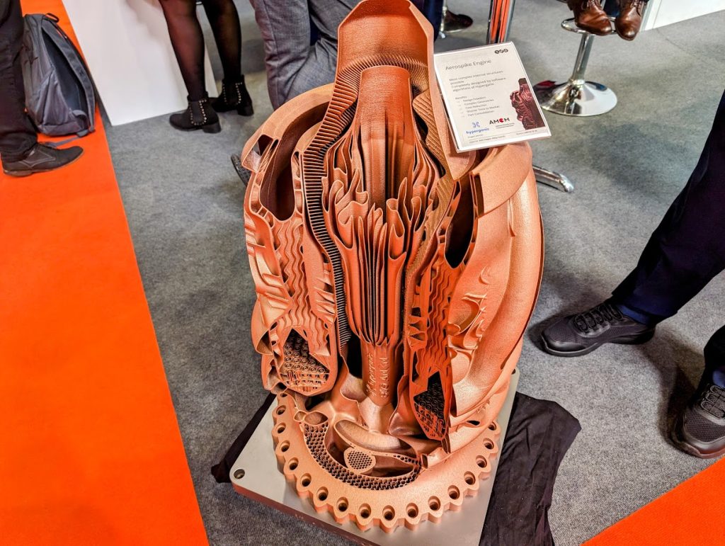
Featured image shows AM Aerospike Engine by AMCM and Hyperganic. An example of the complexity contained within an AM part and a part that required many days to print. Photo by Michael Petch.